


Ethernet Communication Module IFD9507
DVP-PLC Application Manual
16
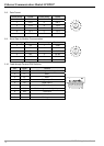
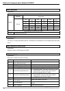
b15 b14 b13 b12 b11 b10 b9 b8 b7 b6 b5 b4 b3 b2 b1 b0
Device
16
Device
15
Device
14
Device
13
Device
12
Device
11
Device
10
Device
9
Device
8
Device
7
Device
6
Device
5
Device
4
Device
3
Device
2
Device
1
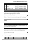
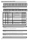
MB#214: Monitored Status
Explanations:
Every MB records the status in the 16-bit device. 1 = normal; 0 = abnormal.
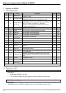
b15 b14 b13 b12 b11 b10 b9 b8 b7 b6 b5 b4 b3 b2 b1 b0
Device
16
Device
15
Device
14
Device
13
Device
12
Device
11
Device
10
Device
9
Device
8
Device
7
Device
6
Device
5
Device
4
Device
3
Device
2
Device
1
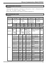
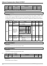
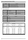
5.2 Monitor Word Registerss (MW)
MW# Attribute Content Explanation Default Latched
0 R/W
Number of devices
monitored
Cache mode normally enabled (b15=1),
monitoring data in max. 16 slaves.
0 YES
1 R/W
No. of station
monitored
No. of the station to be monitored 0 YES
2 R/W
Address of the
device monitored
Recording the address of the device
monitored
0 YES
3 ~ 32 R/W
No. of station
monitored, address
of the device
monitored
No. of the station to be monitore; recording
the address of the device monitored.
0 YES
33 ~ 200 R/W Reserved
201 ~ 216 R Monitored value
Every MW records the monitored value in 1
register
0 NO
216 ~ 300 R Reserved
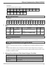
301 R Monitored status
Every MW records the status in a 16-bit
register. 1 = normal; 0 = abnormal
0 NO
Symbol “R” refers to read only; “R/W” refers to read and write.
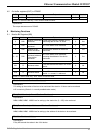
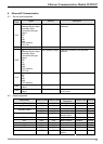
MW#0: Number of Devices Monitored
Explanations:
For setting up the number of devices to be monitored. Max. data in 16 slaves can be monitored.
b15 is read only (Default =1: normally enabled cache mode)
MW# (Odd Number): No. of Station Monitored
Explanations:
MW#1, MW#3, MW#5…MW#33 are for setting up the station No. (0 ~ 255) to be monitored.
MW# (Even Number): Address of Device Monitored
Explanations:
MW32, MW34, MW#36…MW#34 are for setting up the address of the device to be monitored.
MW#201~#216: Monitored Value