


Ethernet Communication Module IFD9507
DVP-PLC Application Manual
18
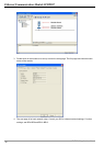
Parameter Explanation
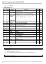
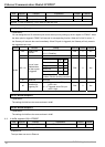
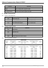
Multiple Max. timeout times
Trigger Cyclic, changing status, application object
OÆT packet interval Packet interval between originator and target
TÆO packet interval Packet interval between originator and target
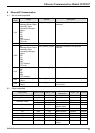
8 Modbus Communication
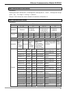
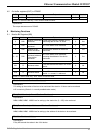
8.1 Function Codes Supported
Function code Explanation Devices supported
0x02 Read discrete input RX
0x03 Read holding register BR, AL, MB, MW, MIP
0x06 Write single holding register BR, AL, MB, MW, MIP
0x10 Write multiple holding register BR, AL, MB, MW, MIP
0x17 Read/write multiple holding register BR, AL, MB, MW, MIP
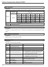
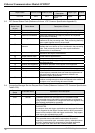
8.2 Exception Codes Supported
Exception code Explanation
0x01 Illegal function
0x02 Illegal data addresss
0x03 Illegal data value
0x04 Slave device failure
0x0A Gateway path unavailable
0x0B Gateway target device failed to respond
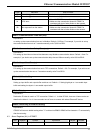
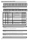
8.3 Device Type & Device Address
Discrete input
Device
type
Modbus address
(Hex)
5-digit Modbus address (Dec)
6-digit Modbus address
(Dec)
Number
RX 0x0400 ~ 0x0402 11025 ~ 11027 101025 ~ 101027 3
Holding register
Device
type
Modbus address
(Hex)
5-digit Modbus address (Dec)
6-digit Modbus address
(Dec)
Number
BR 0x0000 ~ 0x00FF 40001 ~ 40256 400001 ~ 400256 64
AL 0x0200 ~ 0x0202 40513 ~ 40515 400513 ~ 400515 3
X 0x0400 ~ 0x0402 41025 ~ 41027 401025 ~ 401027 3
IN 0x0500 ~ 0x05FF 41281 ~ 41536 401281 ~ 401536 256
OUT 0x0600 ~ 0x06FF 41537 ~ 41791 401537 ~ 401791 256
MB 0x2000 ~ 0x20FF 48193 ~ 48448 408193 ~ 408448 256
MW 0x2200 ~ 0x23FF 48705 ~ 49216 408705 ~ 409216 512
MIP 0x2400 ~ 0x24FF 49217 ~ 49471 409217 ~ 409471 256