


Ethernet Communication Module IFD9507
DVP-PLC Application Manual
15
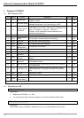
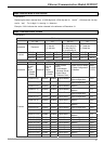
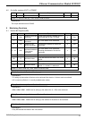
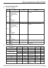
4.5 Out buffer registers (OUT) in IFD9507
OUT# Attribute Content Explanation Default Latched
0~255 R Data output buffer 0 No
Symbol “R” refers to read only; “R/W” refers to read and write.
Explanations:
The output data was sent to RS-485.
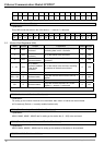
5 Monitoring Functions
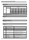
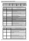
5.1 Monitor Bit Registers (MB)
MB# Attribute Content Explanation Default Latched
0 R/W
Number of devicees
monitored
Cache mode normally enabled (b15=1),
monitoring data in max. 16 slaves.
0 Yes
1 R/W
No. of station
monitored
No. of the station to be monitored 0 Yes
2 R/W
Address of the
device monitored
Recording the address of the device
monitored.
0 Yes
3 ~ 32 R/W
No. of station
monitored, address
of the device
monitored
No. of the station to be monitored;
recording the address of the device
monitored.
0 Yes
33 ~ 200 R/W Reserved
201 R Monitored value
Every MB records the value in the 16-bit
device.
0 No
202 ~ 213 R Reserved
214 R Monitored status
Every MB records the status in the 16-bit
device. 1 = normal; 0 = abnormal
0 No
Symbol “R” refer to read only; “R/W” refers to read and write.
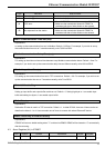
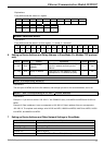
MB#0: Number of Devices Monitored
Explanations:
For setting up the number of devices to be monitored. Max. data in 16 slaves can be monitored.
b15 is read only (Default =1: normally enabled cache mode)
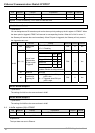
MB# (Odd Number): No. of Station Monitored
Explanations:
MB#1, MB#3, MB#5…MB#33 are for setting up the station No. (0 ~ 255) to be monitored.
MB# (Even Number): Address of Device Monitored
Explanations:
MB#2, MB#4, MB#6…MB#34 are for setting up the address of the device to be monitored.
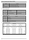
MB#201: Monitored Value
Explanations:
Every MB records the values in the 16-bit device.