


10/100 Fast Ethernet Switch User’s Guide
10
Identifying External Components
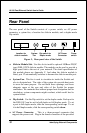
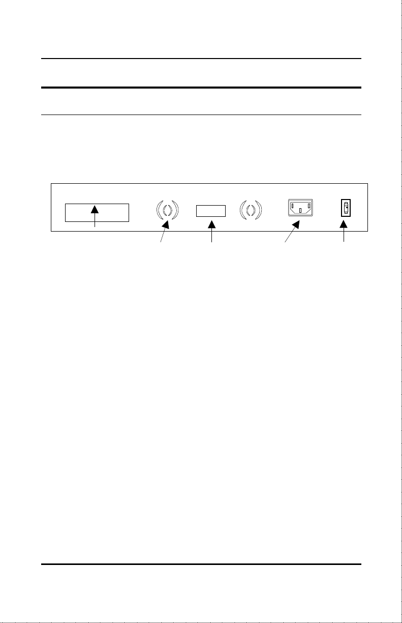
Rear Panel
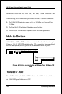
The rear panel of the Switch consists of a power switch, an AC power
connector, a system fan, a location for slide-in module, and a duplex-mode
Dip switch.
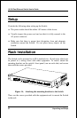
Figure 3, Rear panel view of the Switch
♦
Slide-in Module Slot.
Use this slot to install a optional 100Base-FX(SC
type) DES-112FX slide-in module. The module can be used to provide a
high speed link to the rest of your network. The detail specification of
this module please see Appendix C. And when the slide-in module is
fitted, port 12 automatically switches to become the slide-in module port.
♦
System Fan.
This fan is used to circulate air inside the Switch and
also to dissipate heat. The sides of the system also provide heat vents
to serve the same purpose. Do not block these openings, and leave
adequate space at the rear and sides of the Switch for proper
ventilation. Be reminded that without proper heat dissipation and air
circulation, system components might overheat, which could lead to
system failure.
♦
Dip Switch.
Use this Dip switch to set the duplex mode. Each port in
the DES-1012 can be set for half duplex or full duplex mode. To set
a port in full duplex mode, slide the corresponding switch
up
. To set
it in half duplex mode, slide the corresponding switch
down
.
♦ AC Power Connector.
This is a three-pronged connector that
supports the power cord. Plug in the female connector of the provided
Location for
slide-in module
Dip switch for
Duplex mode
AC Power
Connector
Power
switch
System
Fan