


10/100 Fast Ethernet Switch User’s Guide
Identifying External Components
11
power cord into this connector, and the male into a power outlet.
Supported input voltages range from 100 ~ 240 VAC at 50 ~ 60 Hz.
♦ Power Switch.
This turns the Switch on and off. To turn on the
system, press the switch to the “1” position; to turn off, press the
switch to the “0” position.
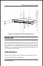
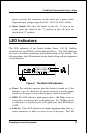
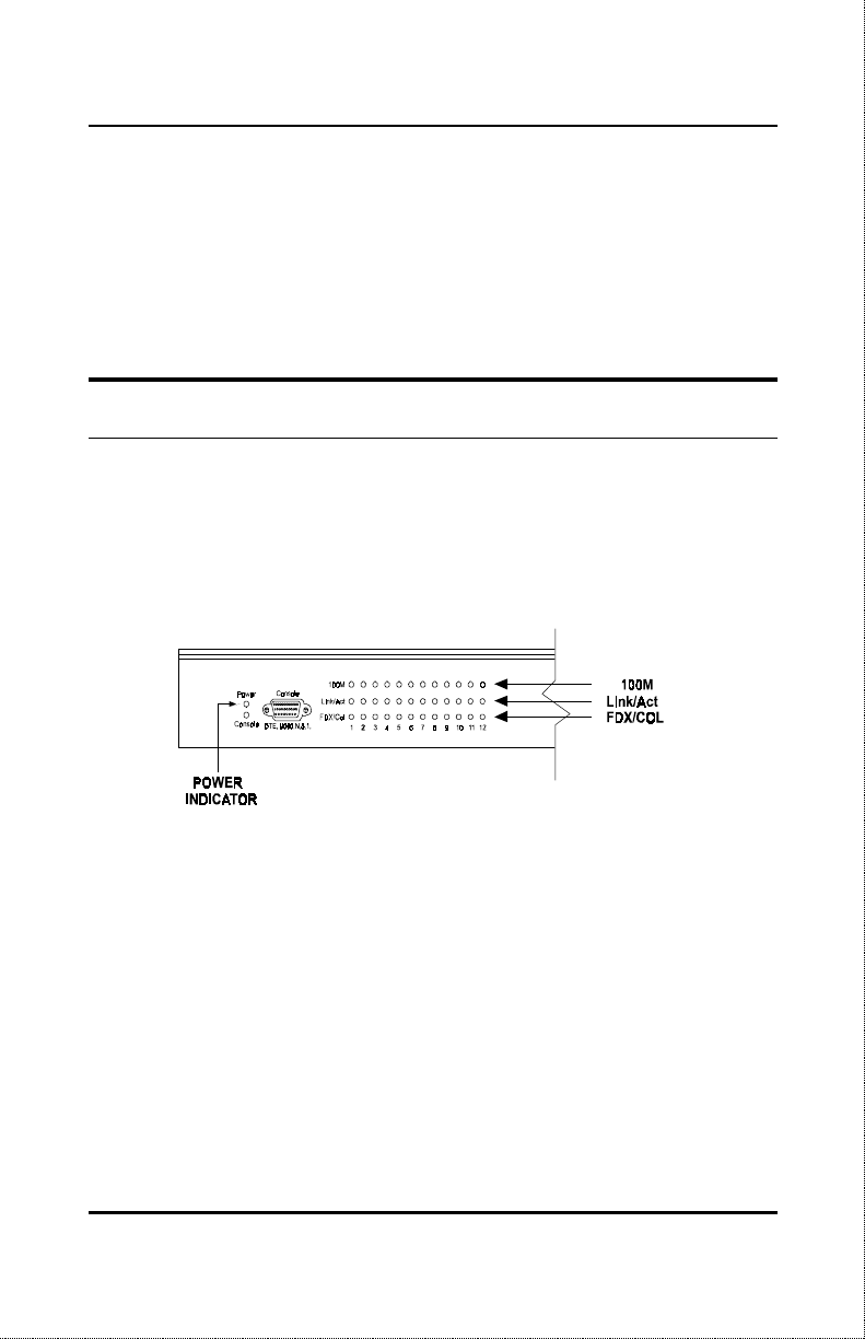
LED Indicators
The LED indicators of the Switch include Power, 100 M, Link/Act
(Link/Activity) and FDX/Col (Full-duplex/Collision). The LED indicators
are used to facilitate monitoring and troubleshooting of the Switch. The
following shows the LED indicators for the Switch along with an explanation
of each indicator.
Figure 4, The Switch LED indicators
♦ Power
. This indicator
operates
when
the
Switch
is turned on. If this
indicator is not lit, check the AC power connector to ensure proper
insertion of the power cord and that the power switch is turned ON.
♦ 100M
. The LED indicator lights
green
when a 100 Mbps device is
connected to a respective port or the uplink port. If a 10 Mbps device
is connected to a respective port or the uplink port, the LED indicator
is OFF.
♦ Link/Act
. These LED indicators are lighted up
green
when there is a
secure connection (or link) to a device at any of the ports. The LED