


8
3. Hardware installation
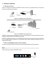
3.1 Operation Overview
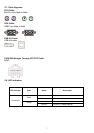
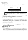
Figure 3-1 shows the connections of DKVM-IP1 switch to its host, to peripheral devices, to the power
source and to the local area network.
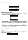
Figure 3-1.a: DKVM-IP1 switch usage scenario
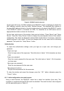
Figure 3-1.b: DKVM-IP1 switch usage scenario
DKVM-IP1 switch redirects local keyboard, mouse, and video data to a remote administration console.
All data is transmitted with the TCP/IP protocol family.
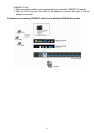
DKVM-IP1 switch can be used in a multi administrator and multi server environment as well. Attaching
one or several DKVM-IP1 switches to a KVM switch matrix allows accessing multiple servers on a
single remote console.
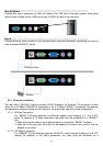
3.2 Connecting DKVM-IP1 switch to the host system
In order to connect the DKVM-IP1 switch of the host system performs the following steps:
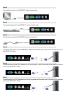
Step 1
Connect the power supply on DKVM-IP1 switch
Administrator
IP Network
DKVM-IP1
KVM Cable
Administrator
IP Network
DKVM-IP1
8/16 PS/2
KVM Switch
KVM Cable
PC/Servers
PC/Servers