


EM78612
Universal Serial Bus Microcontroller
8 •
••
• Product Specification(V1.0) 03.22.2006
(This specification is subject to change without further notice)
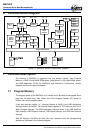
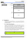
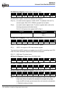
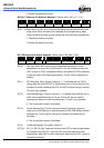
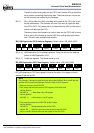
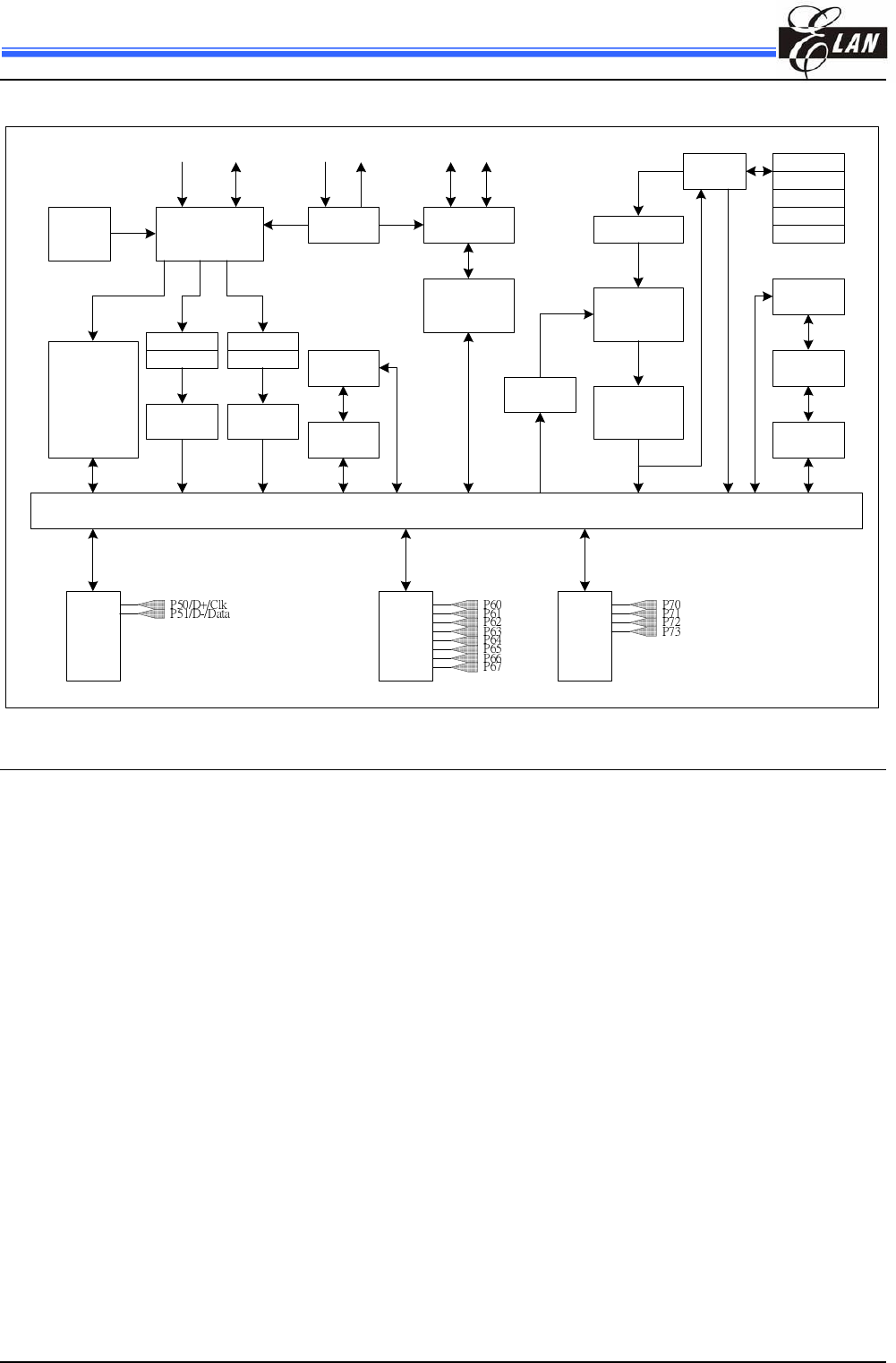
6 Function Block Diagram
Oscillator
Timing
Control
Built-in
RC
Prescaler
R1
(TCC)
WDT
Timer
DATA & CONTROL BUS
OSCI OSCO
R2
(PC)
Stack1
ALU
ACC
R3
(Status)
ROM
Instruction
register
Instruction
Decoder
Interrupt
Control
Reset &
Sleep &
Wake up
Control
3.3V
Regulator
USB
Device
Controller
VDD V3.3
Transceiver
D+ D-
TCCWDT
RAM
R4
(RSR)
Stack2
Stack3
Stack4
Stack5
Prescaler
I/O
Port 7
I/O
Port 6
I/O
Port 5
Figure 6-1 EM78612 Series Function Block Diagram
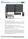
7 Function Description
The memory of EM78612 is organized into four spaces, namely; User Program
Memory in 2048*13 bits MASK ROM space, Data Memory in 80 bytes SRAM space,
and USB Application FIFOs (for EndPoint0 and EndPoint1). Furthermore, several
registers are used for special purposes.
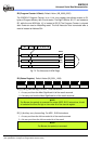
7.1 Program Memory
The program space of the EM78612 is 2K words, and is divided into two pages. Each
page has 1K words long. After Reset, the 12-bit Program Counter (PC) points to
location zero of the program space.
It has two interrupt vectors, i.e., Interrupt Vectors at 0x0001 and USB Application
Interrupt Vectors at 0x000A. The Interrupt Vector applies to TCC Interrupt, and Port 5
State Changed Interrupt. The USB Application Interrupt Vector is for USB EndPoint
Zero Interrupt, USB Suspend Interrupt, USB Reset interrupt, and USB Host Resume
Interrupt.
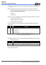
After an interrupt, the MCU will fetch the next instruction from the corresponding
address as illustrated in the following diagram.