


Quick Installation Guide
00825-0100-4075, Rev BA
February 2010
Smart Wireless THUM Adapter
5
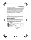
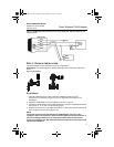
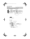
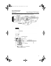
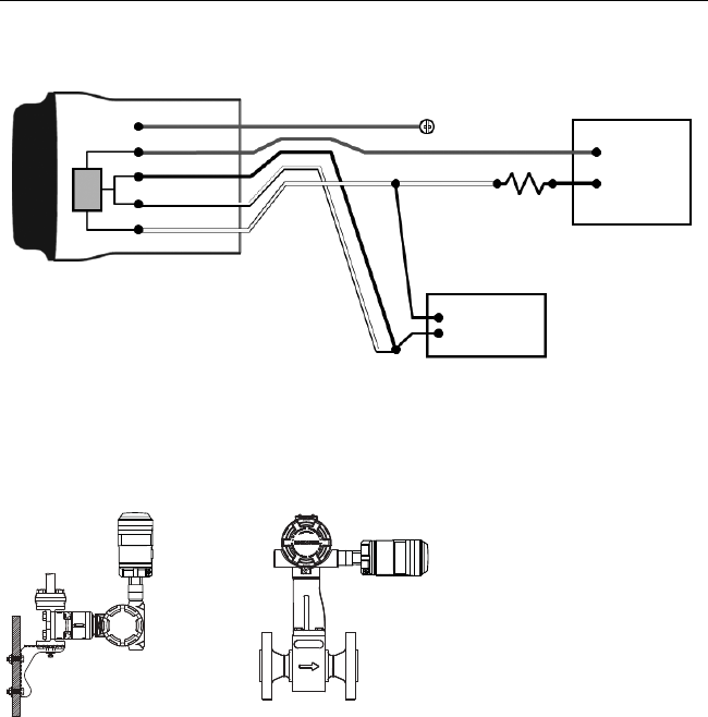
Figure 3. THUM Adapter Only, Powered by a 24 V Power Supply with 1200 Ohm resistor to limit
current to 20 mA
STEP 1: PHYSICAL INSTALLATION
The THUM Adapter can be installed in one of two configurations:
Direct Mount: The THUM Adapter is connected directly to the conduit entry of the wired
device.
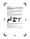
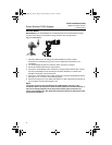
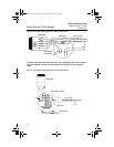
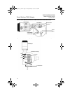
Figure 4. Direct Mount
Direct Mount
1. Install the HART
device according to standard installation practices and the
manufacturer’s instructions, being sure to use an approved thread sealant on all
connections.
2. Attach the THUM Adapter to the wired device as shown in Figure 4.
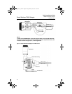
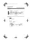
3. Connect the THUM Adapter to the HART wired device using the wiring diagrams below.
See Figures 21, 8, 10, and 12 on the following pages.
4. Close the housing cover on the HART wired device, so that metal touches metal, but do
not over tighten to prevent damaging the unit.
NOTE
Two splice connectors are included with the THUM Adapter. The first is a two
connection splice. The second is a three connection splice for use with a resistor, if
there is not enough resistance in the loop. Both of these splice connectors can
accept 14 to 22 gauge wire. See wired device reference manual for information on the
required loop resistance.
Ground
-
20 mA
Current
Source
HART
Modem
THUM Adapter
Green
Red
Black
White
Yellow
+
1200
Ohm
Resistor
4075_QIG_Rev_BA.fm Page 5 Friday, February 19, 2010 11:08 AM