


Installation Drawings
Liebert
®
NX
™
14
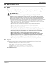
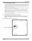
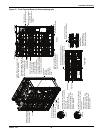
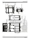
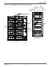
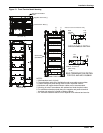
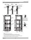
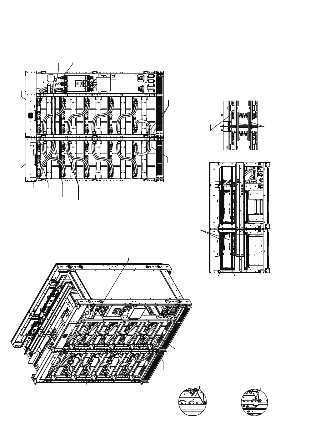
Figure 10 Front Terminal Battery Cabinet shipping split
Install M10 washer, lockwasher
and bolt to secure units together
front and rear
Note: Jar 28 must be
moved forward or removed
to install rear hardware. Rear
cutouts are provided if rear
access is provided.
Install M10 washer, lockwasher
and bolt to secure units together
front and rear
Note: Jar 16 must be
moved forward or removed
to install rear hardware. Rear
cutouts are provided if rear
access is provided.
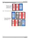
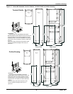
Install snap bushing
in corner post before
routing these wires
Install snap bushing
in corner post before
routing these wires
Install snap
bushing
in corner
post before
routing these
wires
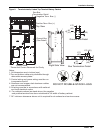
Route two supplied wires (W17)
from Jar 15 (+) to Jar 16 (-)
Note: Install bushing first.
Route two supplied wires (W16)
from Jar 1 (-) to BCB breaker in (-)
Note: Install bushings first.
Tywrap here to
secure wires in place
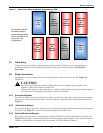
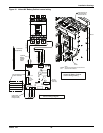
Use M10 hardware
supplied on bus
Torque to 240 in-lb
(27Nm)
Use M8 hardware supplied on bus
Torque to 180 in-lb (20Nm)
Remove M6 hardware
used to secure lugs
in place and discard
Connect lugs to bus
directly above insulator
and secure with M8 hardware
supplied on bus. Typ 8 places.
Torque to 180 in-lb (20Nm)
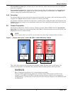
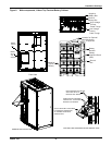
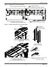
Cabinet A Cabinet B
Remove these busbars and keep
the hardware to secure busbars
between Cabinet A & Cabinet B
Negative (-)
Positive (+)
Busbars shown
connected between
Cabinet A & Cabinet B
(busbar quantity varies)
Reuse M12 hardware
Torque to 480 in-lb (54Nm)
Jar 16
Jar 28
A
B
Tywrap here to
secure wires in place
Tywrap here to
secure wires in place
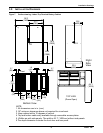
Top View
Front
Detail A
Detail B
Isometric View