Installation Drawings
Liebert
®
NX
™
20
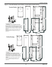
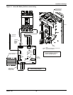
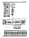
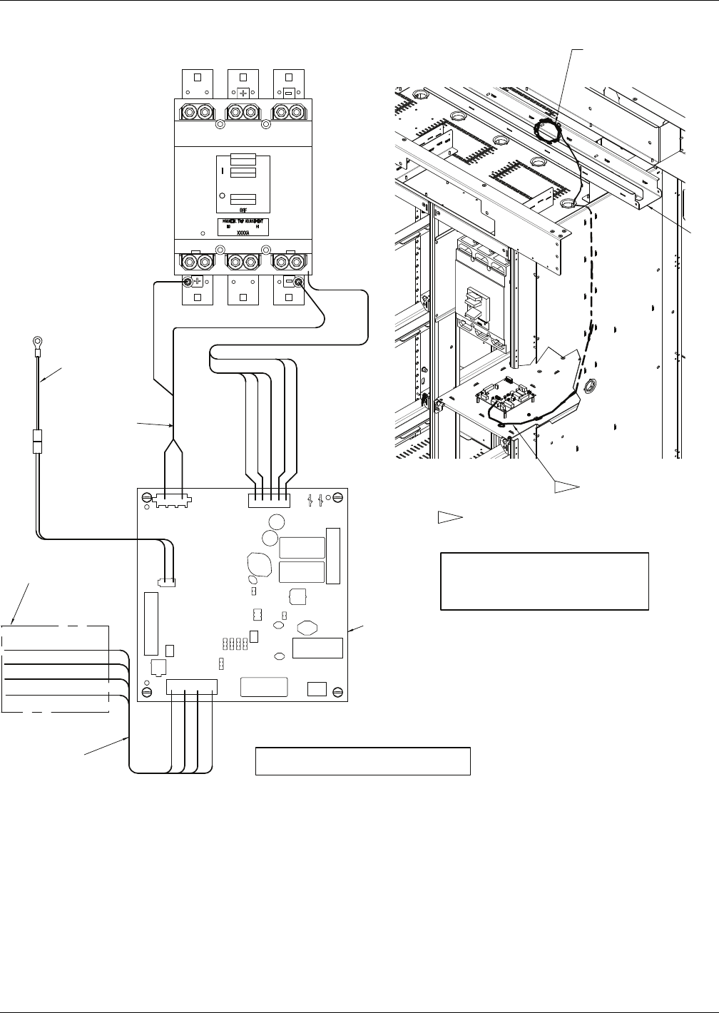
Figure 16 Liebert NX Battery Cabinet control wiring
1
1
NOTES
USE WIRE TIE AS NECCESSARY FOR ROUTING AND
SECURING WIRE HARNESSES.
TROUGH
CAN cable to be run
in trough closest to
the front of the unit
BATTERY
INTERFACE
BOARD (BIB)
24V (RED)
GND (BLK)
CANH (WHT)
CANL (BLK)
AUX. CONTACT 1
AUX. CONTACT 1
AUX. CONTACT 1
UVR TRIP - Optional
UVR TRIP- Optional
1 2 3 4 5
7 6 5 4 3 2 1
1 2 3
2 1
+24V (RED)
GND (BLK)
CANL (BLK)
CANH (WHT)
TB1150
TB1151
TB1154
TB1156
TB1158
( BATTERY
MONITORING
SYSTEM )
P1153
(BLK)
(RED)
This end field-connected
to other cabinets
P1152
Thermistor
(Optional)
Optional
Battery
Voltage
Sense
Cable
CAN Cable
(Belden 9156
or Equivalent)
1- BRKR- NEG
3-BRKR-POS
Control Wiring Diagram
Liebert NX Battery Cabinet
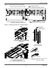
Control Wiring Routing
4321


