


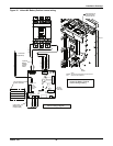
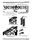
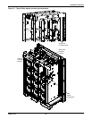

Installation Drawings
Liebert
®
NX
™
24
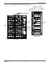
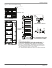
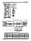
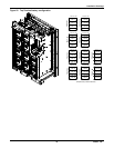
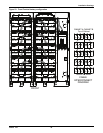
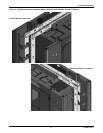
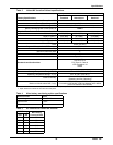
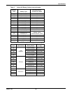
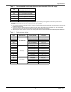
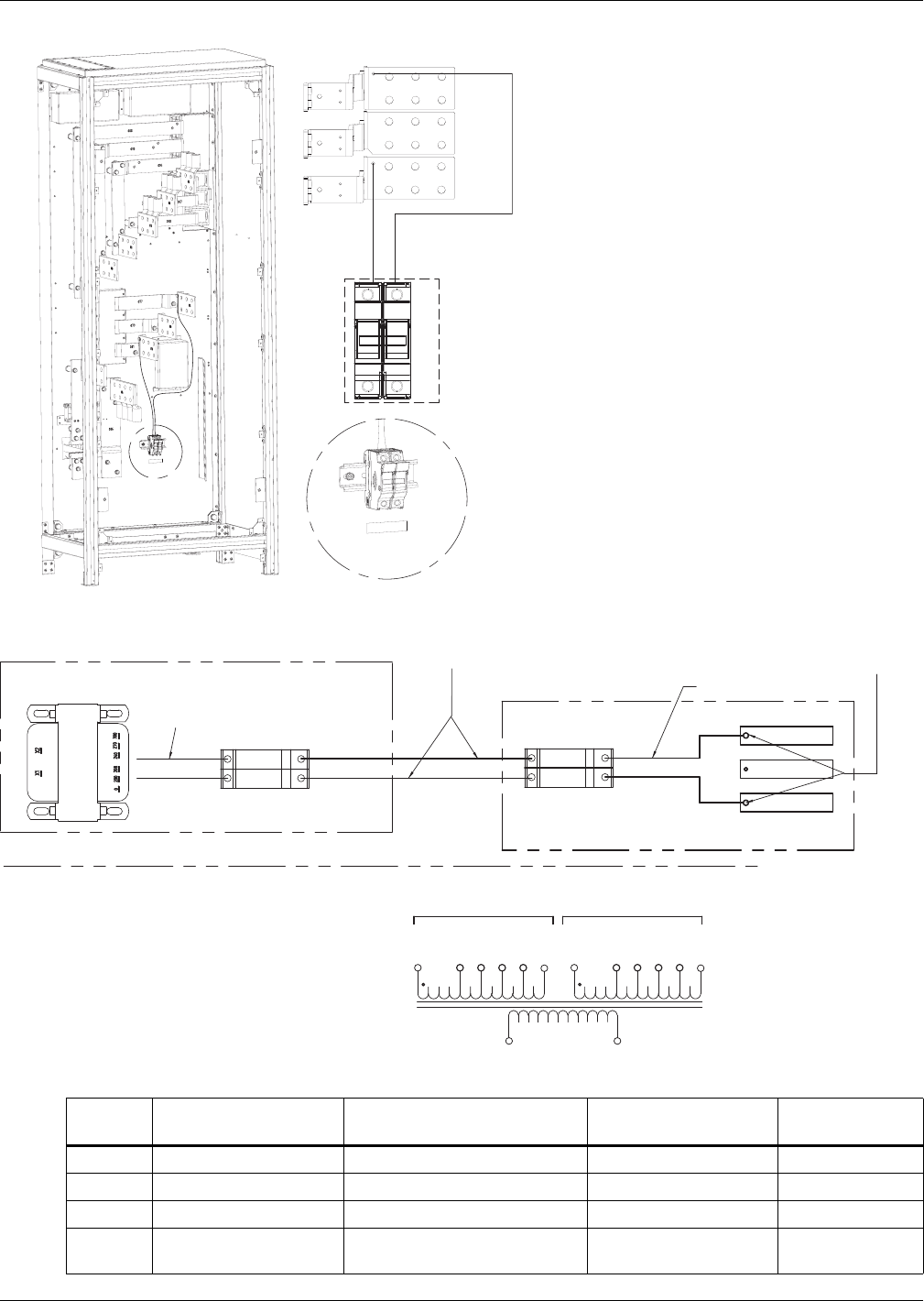
Figure 21 Alber battery monitoring assembly diagram
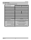
Table 1 Alber battery monitoring assembly connections
Input
Voltage
Alber Transformer-2
(Wht) Jumper
Alber Transformer-1
(Blk)
F4-F5
Fuse Rating
600 0 (Top) 300 (Top) to 0 (Bottom) 300 (Bottom) 2.25 A, 600VAC
480 0 (Top) 240 (Top) to 0 (Bottom) 240 (Bottom) 1.25 A, 600VAC
380 0 (Top) 300 (Top) to 208 (Bottom) 300 (Bottom) 1 A, 600VAC
208 0 (Top)
0 (Top) to 0 (Bottom) and
208 (Top) to 208 (Bottom)
208 (Top) 0.75A, 600VAC
F76
F75
NX BATTERY CABINET
UPS MODULE OUTPUT
XFMR CONNECTION DIAGRAM
Harness factory-installed.
Verify transformer connection
Prior to startup.
See diagram below.
ALBER BATTERY
MONITORING XFMR
This harness is intended for use only when
battery cabinet is connected directly to UPS.
For all other instances, customer must supply wire.
TOP TERMINALS
FROM F5 FUSE IN BAT CAB
BOTTOM TERMINALS
FROM F4 FUSE IN BAT CAB
F5
F4
V_OUT_A
V_OUT_C
Wire Harness
Secure supplied wire
harness to busbar with
supplied hardware.
X1
X2
0 V
270 V
208 V
240 V
300 V
200 V
0 V
270 V
208 V
240 V
300 V
200 V
230 V
Output A
Output B
Output C
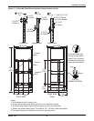
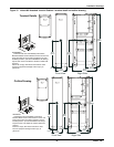
FH2-1
FH2-2
FH2
A
Detail A
FH2-1
FH2-2
Optional