ii
FIGURES
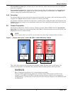
Figure 1 Shipping bolts—Top-Terminal Battery Cabinet . . . . . . . . . . . . . . . . . . . . . . . . . . . . . . . . . . . . . . . . 4
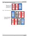
Figure 2 Battery cabinets connected, attached to UPS . . . . . . . . . . . . . . . . . . . . . . . . . . . . . . . . . . . . . . . . . . 7
Figure 3 Battery cabinets connected, detached from UPS . . . . . . . . . . . . . . . . . . . . . . . . . . . . . . . . . . . . . . . 7
Figure 4 Stand-alone battery cabinets, detached from UPS . . . . . . . . . . . . . . . . . . . . . . . . . . . . . . . . . . . . . . 8
Figure 5 Control cable layout—Liebert NX UPS to Liebert NX Battery Cabinet . . . . . . . . . . . . . . . . . . . . . 9
Figure 6 Battery temperature sensor control connection . . . . . . . . . . . . . . . . . . . . . . . . . . . . . . . . . . . . . . . 10
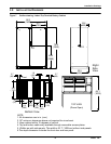
Figure 7 Outline drawing, Liebert Top-Terminal Battery Cabinet . . . . . . . . . . . . . . . . . . . . . . . . . . . . . . . 11
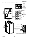
Figure 8 Main components, Liebert Top-Terminal Battery Cabinet . . . . . . . . . . . . . . . . . . . . . . . . . . . . . . 12
Figure 9 Terminal details, Liebert Top-Terminal Battery Cabinet . . . . . . . . . . . . . . . . . . . . . . . . . . . . . . . 13
Figure 10 Front Terminal Battery Cabinet shipping split . . . . . . . . . . . . . . . . . . . . . . . . . . . . . . . . . . . . . . . 14
Figure 11 Front Terminal Battery Cabinet outline drawing. . . . . . . . . . . . . . . . . . . . . . . . . . . . . . . . . . . . . . 15
Figure 12 Front Terminal Battery Cabinet main components, layout . . . . . . . . . . . . . . . . . . . . . . . . . . . . . . 16
Figure 13 Front Terminal detail drawing. . . . . . . . . . . . . . . . . . . . . . . . . . . . . . . . . . . . . . . . . . . . . . . . . . . . . 17
Figure 14 Liebert NX Stand-Alone Junction Cabinet terminal wiring . . . . . . . . . . . . . . . . . . . . . . . . . . . . . 18
Figure 15 Liebert NX Attached Junction Cabinet—terminal detail and outline drawing . . . . . . . . . . . . . . 19
Figure 16 Liebert NX Battery Cabinet control wiring. . . . . . . . . . . . . . . . . . . . . . . . . . . . . . . . . . . . . . . . . . . 20
Figure 17 Attached battery cabinet connections . . . . . . . . . . . . . . . . . . . . . . . . . . . . . . . . . . . . . . . . . . . . . . . 21
Figure 18 Ground strap location for connected cabinets . . . . . . . . . . . . . . . . . . . . . . . . . . . . . . . . . . . . . . . . . 21
Figure 19 Typical Alber battery monitoring connections . . . . . . . . . . . . . . . . . . . . . . . . . . . . . . . . . . . . . . . . 22
Figure 20 Alber battery monitoring wiring to multiple battery cabinets . . . . . . . . . . . . . . . . . . . . . . . . . . . . 23
Figure 21 Alber battery monitoring assembly diagram. . . . . . . . . . . . . . . . . . . . . . . . . . . . . . . . . . . . . . . . . . 24
Figure 22 Top-Terminal battery configuration . . . . . . . . . . . . . . . . . . . . . . . . . . . . . . . . . . . . . . . . . . . . . . . . 25
Figure 23 Front-Terminal battery configuration . . . . . . . . . . . . . . . . . . . . . . . . . . . . . . . . . . . . . . . . . . . . . . . 26
Figure 24 Busbar connection between Battery Cabinet and Attached Junction Cabinet . . . . . . . . . . . . . . . 27
TABLES
Table 1 Alber battery monitoring assembly connections . . . . . . . . . . . . . . . . . . . . . . . . . . . . . . . . . . . . . . . 24
Table 2 Liebert NX Battery Cabinet specifications . . . . . . . . . . . . . . . . . . . . . . . . . . . . . . . . . . . . . . . . . . . 28
Table 3 Liebert NX Junction Cabinet specifications . . . . . . . . . . . . . . . . . . . . . . . . . . . . . . . . . . . . . . . . . . 29
Table 4 Alber battery monitoring option specifications . . . . . . . . . . . . . . . . . . . . . . . . . . . . . . . . . . . . . . . . 29
Table 5 DC currents for Liebert NX modules . . . . . . . . . . . . . . . . . . . . . . . . . . . . . . . . . . . . . . . . . . . . . . . . 29
Table 6 Liebert NX Battery Cabinet internal breaker. . . . . . . . . . . . . . . . . . . . . . . . . . . . . . . . . . . . . . . . . 30
Table 7 Liebert NX Battery Cabinet approximate weights . . . . . . . . . . . . . . . . . . . . . . . . . . . . . . . . . . . . . 30
Table 8 Recommended conduit and cable sizes from Liebert NX UPS to DC supply. . . . . . . . . . . . . . . . . 31
Table 9 Battery torque values . . . . . . . . . . . . . . . . . . . . . . . . . . . . . . . . . . . . . . . . . . . . . . . . . . . . . . . . . . . . 31
Table 10 Torque specifications, unless otherwise labeled . . . . . . . . . . . . . . . . . . . . . . . . . . . . . . . . . . . . . . . 32


