


Operating Instructions
95
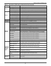
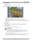
11.1.1 Circuit Breakers
The UPS can be isolated by means of circuit breakers, mounted inside the cabinet and accessible after
opening the front door.
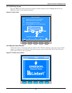
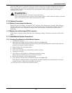
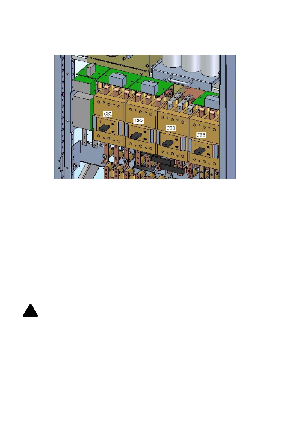
The location of the UPS power switches is shown in Figure 66.
Figure 66 Circuit breakers
The UPS unit circuit breakers are CB1, CB2, CB3 and CB5.
• CB1—Main Input circuit breaker; connects the utility supply to the UPS main input.
• CB2—Bypass circuit breaker; connects the utility supply to the UPS bypass.
• CB3—Maintenance Bypass breaker; connects the utility supply to the UPS maintenance bypass.
• CB5—Output breaker; connects inverter or bypass to the external output transformer or power
distribution panel.
11.2 UPS Startup
The Liebert
®
NX
™
must be fully installed and commissioned before startup, and external power
isolators must be closed. Once those general conditions are met, the UPS may be started.
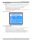
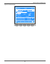
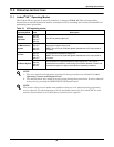
11.2.1 Startup Procedure
To start the UPS from a fully powered-down condition:
1. Open the UPS door to gain access to the main input circuit breakers.
2. Close CB1, CB2 and CB3 (CB5 is open).
The main input contactor closes automatically and the LCD begins to show startup screens. The
Rectifier indicator flashes green while the rectifier is starting up. It stops flashing and becomes
solid green about 30 seconds after the rectifier enters the normal operation state.
!
WARNING
Risk of electrical shock. Can cause injury and death.
During this procedure the output terminals will become live. If any load equipment is
connected to the UPS output terminals, please check with the load user and ascertain
whether it is safe to apply power to the load. If the load is not ready to receive power, then
ensure that it is safely isolated from the UPS output terminals.