


Operating Instructions
105
11.11.3Shutdown Procedure—Complete UPS and Load Shutdown
This procedure must be followed to completely power down the UPS and the load. All power switches,
isolators and circuit breakers will be opened and power will be removed from the load.
In multi-module systems, perform each step of the procedure in every UPS module before proceeding
to the next step.
NOTICE
Risk of improper operation. Can cause property damage from loss of power to connected load.
This procedure will shut off power to the load. Before beginning this procedure, shut down the
connected load to prevent the possibility of damage.
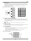
1. Press the EPO (Emergency Power Off) button at the UPS front panel only. This will disable
Rectifier, Inverter, Static Switch and Battery operation. The load will be de-energized.
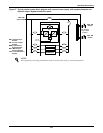
2. Open the UPS door to gain access to the main circuit breakers.
3. Open the Rectifier input circuit breaker CB1.
4. Open external battery circuit breaker. This breaker is inside the battery cabinet or is otherwise
adjacent to the battery racks.
5. Open Output circuit breaker CB5.
6. Open bypass input circuit breaker CB2.
7. Ensure maintenance bypass circuit breaker CB3 is open.
8. All mimic panel LED indications and messages will extinguish as the mains-driven, internal
power supplies decay.
9. To completely isolate the UPS from the AC supplies, the main external power input isolator (both
isolators, where dual supplies are provided for rectifier and bypass) and external output isolator
must be opened and tagged with warning labels accordingly.
11.12 Commissioning a Parallel System
Check the input and output wiring of each UPS module. Ensure that the phase rotation sequence of
the main inputs and the bypass inputs and outputs of each UPS module are the same. Ensure that
the parallel cables are connected firmly.
It is assumed that the installation is complete, the system has been commissioned by authorized
personnel and the external power isolators are closed. Disconnect the load before startup.
11.13 Parallel System Startup
1. Start each UPS normally as described in 11.2 - UPS Startup.
2. Turn on the inverter of each UPS module one at a time.
3. Apply the load after the last UPS module transfers to inverter. The total load can be determined
through the LCD of either UPS.
4. Verify the load rate of each UPS module. If the load rates are roughly the same, then the parallel
system may be assumed to be operating normally.
!
CAUTION
Except in an emergency situation, do not press any remote EPO button.
!
CAUTION
The operations described in this section must be performed by authorized electricians or
qualified technical personnel. If you have any difficulty, call 1-800-LIEBERT for assistance.
NOTE
If one module cannot transfer to inverter mode long after its inverter is on, its output
connection may not be good or its output phase rotation may not be coincident with other
modules. At this time, the LCD for the UPS module will display “inverter asynchronous” and
the inverter indicator will flash continuously. If either UPS module makes abnormal noise
after it transfers to inverter, its parallel cables may be incorrectly connected.