


Options
28
5.0 OPTIONS
5.1 Load Bus Synchronization
The Load Bus Synchronizer (LBS) keeps the output of two independent UPS systems or parallel UPS
systems in synchronization even when the systems are operating in different modes and even when
either or both systems are operating on batteries. When the LBS is used, one UPS system is
designated as master, the other as slave.
The LBS option is typically used with dual-corded equipment or with either the Liebert
®
SmartSwitch
™
or Liebert Static Transfer Switch
™
(STS) for single-corded equipment.
5.1.1 Performance Requirements
The LBS operates under the following conditions:
• Both master and slave are on inverter
(either system may be on inverter through the rectifier or on inverter through the batteries)
• Master on inverter and slave on bypass
• Master on bypass and slave on inverter
• Master and slave on bypass IF the bypass source is the same for both systems
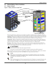
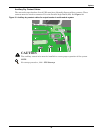
5.1.2 LBS Cable and Settings
For Liebert NX
™
-to-Liebert NX dual bus configuration, only one optional LBS cable is required, the
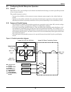
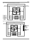
built-in LBS will operate normally without an extra LBS control box or interface box. The LBS port is
X4 on the Parallel Board (M3). The Parallel Board is on the interior of the Liebert NX, above and left
of the power electronics; see Figures 30 and 33.
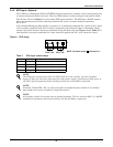
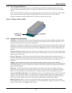
An optional, 9-pin LBS cable is used to connect two UPS systems through each system’s DB9 port on
its Parallel Board. For two parallel systems, the LBS cable can be mounted between any two units
belonging to different parallel systems. For information about the LBS kit or to order the optional
equipment, see your local Liebert representative.
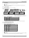
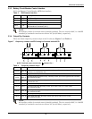
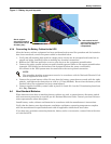
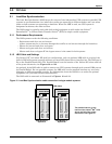
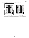
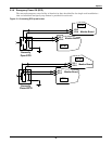
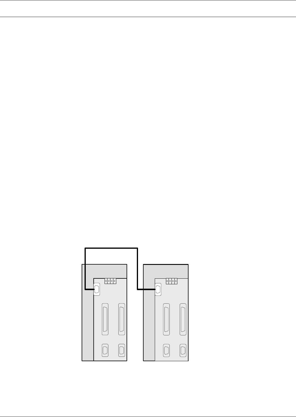
The LBS cable is connected as illustrated in Figures 12 and 13.
Figure 12 Load Bus Synchronization cable connection in single module systems
X1-1 X1-2
X2-1 X2-2
Parallel Board
X4
X1-1 X1-2
X2-1 X2-2
Parallel Board
X4
X3
LBS Cable
UPS Module or
System #1
UPS Module or
System #2
The parallel board is on the
interior of the Liebert
®
NX
™
UPS,
above and left of the power
electronics; see Figure 29.