


Operating Instructions
103
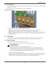
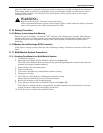
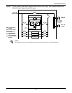
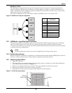
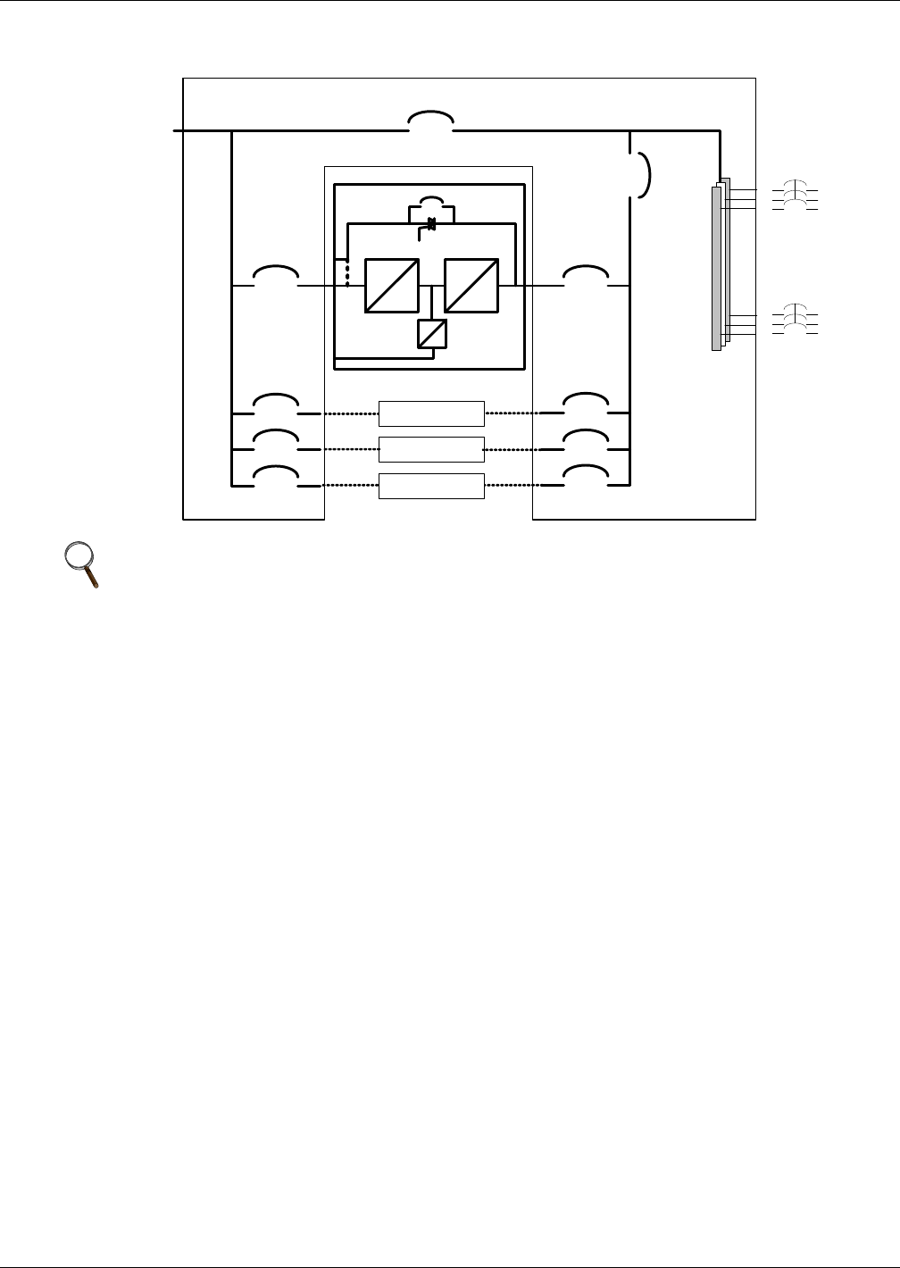
Figure 67 Typical parallel system block diagram with common input supply, with separate batteries and
optional output / bypass distribution panel
NOTE
All equipment servicing procedures must be carried out only by trained personnel.
480V, 3W
System Input
480V, 3W
Output
480V DC
Battery Input
AC
DC
DC
AC
Bypass
Static
Switch
DC
DC
RIB 1
RIB 2
RIB 3
RIB 4 IOB 4
IOB 3
IOB 2
IOB 1
UPS Module 3
MBB
MIB
User Supplied
Plug-In Output
Breakers
480V, 3W
Output
UPS Module 4
UPS Module 2
Liebert NX UPS (40-200kVA)
LDB 1
LDB N
RIB = Rectifier Input
Breaker
IOB = Inverter Output
Breaker
MBB = Maintenance
Bypass Breaker
MIB = Maintenance
Isolation Breaker
LDB = Load Distribution
Breaker