


Electrical Connections
19
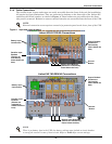
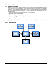
2.3.3 Battery Circuit Breaker Control Interface
J10 is the Battery Circuit Breaker (BCB) box interface.
2.3.4 Output Dry Contacts
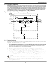
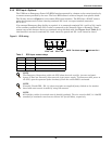
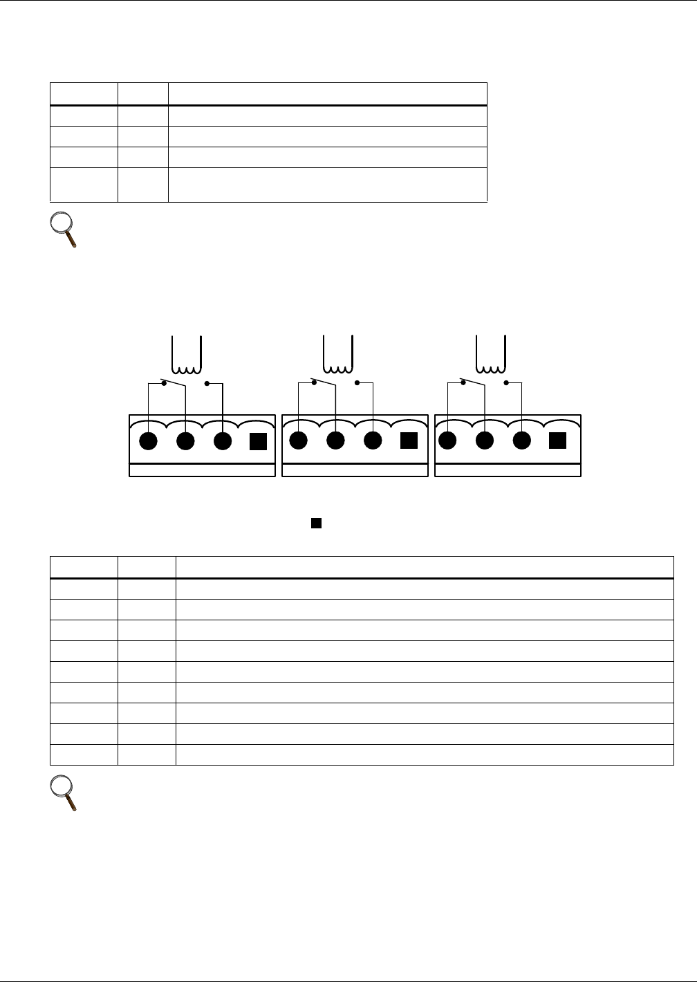
There are three output dry contact relays at the X1 slot (see Figure 8 and Table 4).
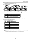
Figure 8 Output dry contacts and EPO wiring for firmware before M170
Table 3 BCB control interface
Position Name Description
J10.1 DRV BCB Driver Signal
J10.2 FB BCB Contact State
J10.3 GND Power Ground
J10.4 OL
BCB On-Line - Input - This pin will become active when
BCB interface is connected. (N.O.)
NOTE
All auxiliary cables of terminal must be double-insulated. The wire must be 600V, 18-16 AWG
stranded for maximum runs between 82 and 197 feet (25-60m), respectively.
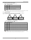
Table 4 Output dry contact relays
Position Name Description
J13.2 BFP_O Bypass feedback protection relay. Normally open. Closed when bypass SCR is shorted.
J13.3 BFP_S Bypass feedback protection relay center
J13.4 BFP_C Bypass feedback protection relay. Normally closed. Open when bypass SCR is shorted.
J21.2 INV_O Inverter mode relay. Normally open. Closed when UPS is in inverter mode.
J21.3 INV_S Inverter mode relay center
J21.4 INV_C Inverter mode relay. Normally closed. Open when UPS is in inverter mode.
J25.2 ACF_O Main input fault relay. Normally open. Closed when main input is in fault.
J25.3 ACF_S Main input fault relay center
J25.4 ACF_C Main input fault relay. Normally closed. Open when main input is in fault.
NOTE
All auxillary cables of terminal must be double-insulated. The wire must be 600V, 18-16 AWG
stranded for maximum runs between 82 and 197 feet (25-60m), respectively.
J25
ACF_O
ACF_S
ACF_C
J21
INV_C
INV_S
INV_O
X1
J13
BFP_C
BFP_S
BFP_O
NOTE: The black square on each slot indicates Pin 1.