


Operating Instructions
83
9.8.2 Inserting One Module into a Multi-Module System
This procedure outlines how to integrate a UPS module that has been previously isolated from other
modules of a group of paralleled UPS modules. It is assumed that the installation is complete, the sys-
tem has been commissioned by authorized personnel and the external power isolators are closed.
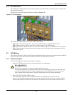
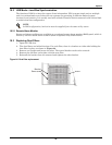
1. Open the UPS door to gain access to the main circuit breakers.
2. Open (or confirm disabled) maintenance bypass circuit breaker CB3.
3. Close Input breaker CB1.
The Rectifier indicator flashes on the UPS mimic panel during the startup of the rectifier and
becomes steady green once the rectifier reaches normal operation state after about 30 seconds.
4. Close external battery circuit breaker. This breaker is inside the battery cabinet or is otherwise
adjacent to the battery racks.
5. After the UPS detects the batteries, the red battery indicator extinguishes when the battery
charger starts operation.
6. Close bypass circuit breaker CB2.
7. Press the INVERTER ON control button for 2 seconds.
The inverter will start up and the inverter indicator flashes while it synchronizes to the load volt-
age and frequency. After the inverter is ready, the UPS connects to the load, the inverter indicator
becomes steady green and the output indicator turns green.
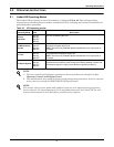
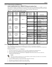
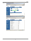
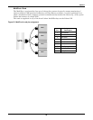
8. Check that no “Warning” message is displayed in the top right corner of the LCD and that the
indicators have the status shown below.
The UPS is now operating in NORMAL mode.
!
WARNING
Mains voltage will be applied to UPS output terminals.
No operator serviceable parts are located behind covers that require a tool for their removal.
Only qualified service personnel are authorized to remove such covers.
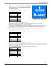
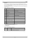
# LED LED Function Status
1 Rectifier indicator Green
2 Battery indicator Off
3 Bypass indicator Off
4 Inverter indicator Green
5 Output indicator Green
6 Alarm indicator Off