Options
31
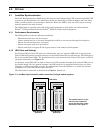
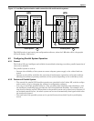
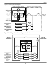
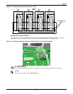
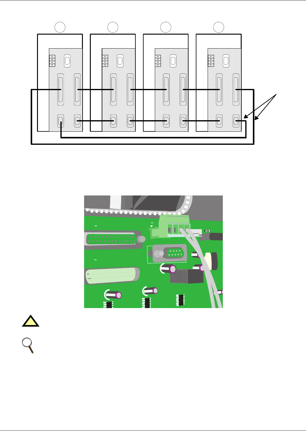
Figure 18 Connecting system parallel control cables
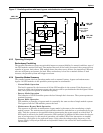
Auxiliary Dry Contact Cables
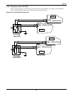
The external output breaker of each UPS must have Normally Open auxiliary contacts. These con-
tacts must be wired to connector X3 on the Parallel Logic Board (M3). See Figure 19.
Figure 19 Auxiliary dry contact cables for output breaker in multi-module system
!
CAUTION
The auxiliary control wire must be installed to ensure proper operation of the system.
NOTE
For startup procedure, 9.2 - UPS Startup.
X1-1 X1-2
X2-2 X2-1
Parallel Board
X4
X3
P5
P3
P4 P1
P2
X1-1 X1-2
X2-2 X2-1
Parallel Board
X4
X3
P5
P3
P4 P1
P2
X1-1 X1-2
X2-2 X2-1
Parallel Board
X4
X3
P5
P3
P4 P1
P2
X1-1 X1-2
X2-2 X2-1
Parallel Board
X4
X3
P5
P3
P4 P1
P2
1 2 3 4
UPS
Interconnecting
Cables
485-
P2 X2
2
485+
DBS
X3
P1 X2
1
:XT M AIN T


