


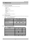
Options
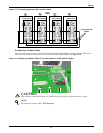
29
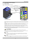
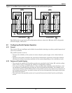
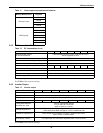
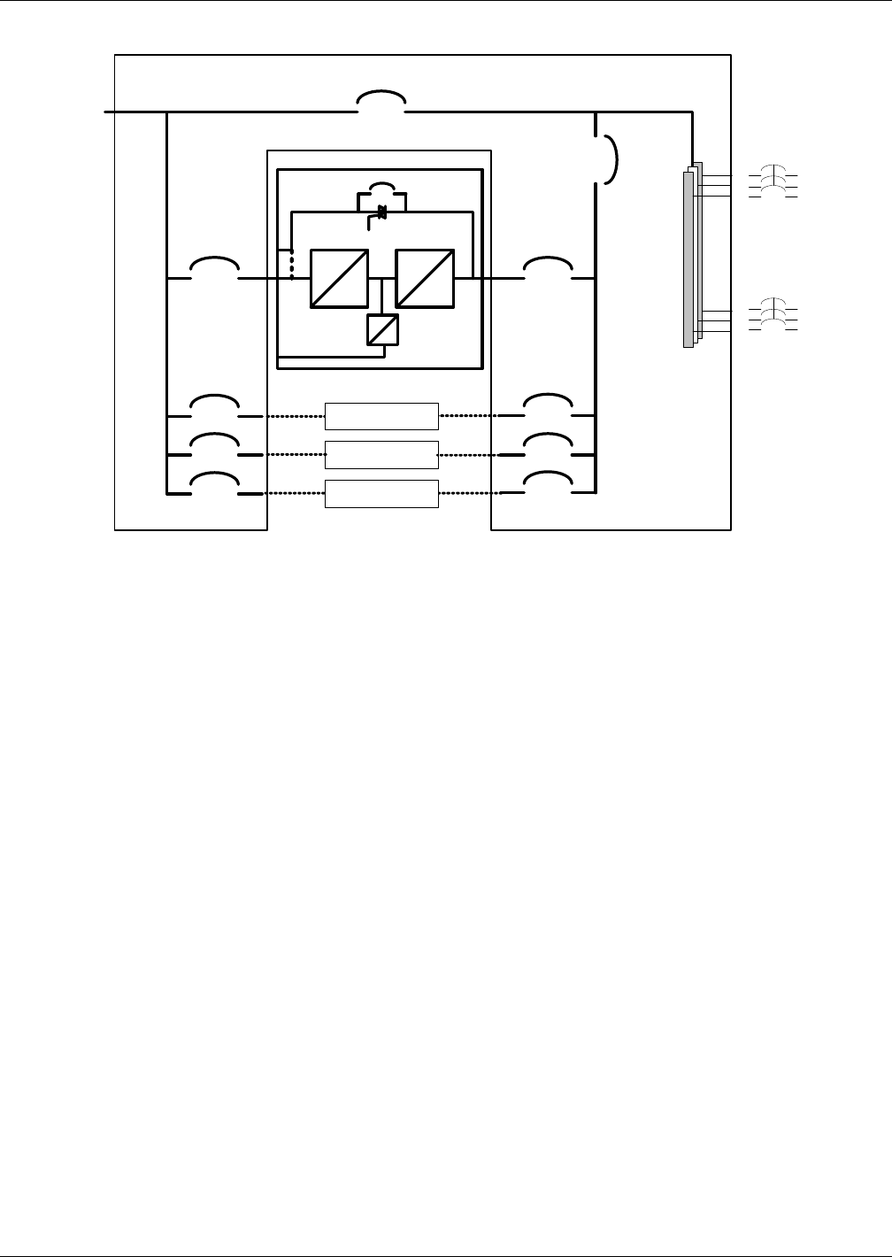
Figure 17 Paralleling cabinet with input, bypass and distribution circuit breakers
4.2.3 Operating Principles
Redundancy Paralleling
The parallel redundant system can noticeably improve system reliability. In normal condition, none of
the UPS modules work at full load. That means that even if the load is increased, the system will not
transfer to bypass. And when a UPS module shuts down due to any failure, the remaining UPS mod-
ules can still power and protect the load. When redundancy is lost due to module failure or load
increase, the parallel system will trigger an alarm.
4.2.4 Operation Modes Summary
The parallel system also has operation modes such as normal, battery, bypass and maintenance
bypass. All UPS modules in the parallel system operate in coordination.
• Normal Mode Operation
The load is powered by the inverters of all the UPS modules in the system. If the frequency of
bypass is within the synchronous range, the inverter will be synchronized with the bypass. Other-
wise, the system will operate at nominal frequency.
• Battery Mode Operation
The batteries of all UPS modules power the load through their inverters. The system operates at
nominal frequency.
• Bypass Mode Operation
The condition to transfer to bypass mode is essentially the same as that of single module system.
The bypass of all the UPS modules powers the load.
• Maintenance Bypass Mode Operation
The sequence to transfer to maintenance bypass mode is the same as for transferring a single-
module system. The maintenance bypass switches should be switched on as synchronously as pos-
sible. Thus the system can be repaired without interrupting the power supply to critical load. If
ECO mode is selected, the double-conversion UPS operation is inhibited at most times for the pur-
pose of saving energy. In this mode of operation, not unlike UPS of line-interactive or standby
technology, the bypass is the preferred source. Only when the voltage and/or frequency of the
bypass supply is beyond pre-defined and adjustable limits is the critical AC load transferred to
the inverter.
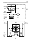
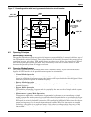
480V, 3W
System Input
480V, 3W
Output
480V DC
Battery Input
AC
DC
DC
AC
Bypass
Static
Switch
DC
DC
RIB 1
RIB 2
RIB 3
RIB 4 IOB 4
IOB 3
IOB 2
IOB 1
UPS Module 3
MBB
MIB
User Supplied
Plug-In Output
Breakers
480V, 3W
Output
UPS Module 4
UPS Module 2
Liebert NX UPS (40-200kVA)
LDB 1
LDB N