Maintenance
107
4.6 Reporting a Problem
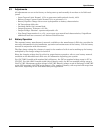
If a problem occurs within the UPS, review all alarm messages along with other pertinent data. This
information should be given by telephone to the Liebert service representative’s office nearest you.
This information can be downloaded to Liebert Global Services by using the optional modem. Contact
Liebert Global Services at 1-800-LIEBERT to report a problem or to request assistance.
4.7 Corrective Actions
For each alarm message on the Operator Control Panel and the Remote Monitor Panel, you can find
the recommended corrective action in Table 9.
4.8 Recommended Test Equipment
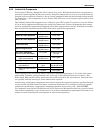
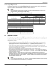
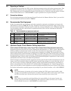
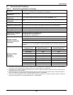
A list of recommended test equipment and tools required to maintain, troubleshoot and repair the
UPS module is given in Table 16. You may substitute instruments of equivalent range and accuracy.
All instruments should be calibrated and be within the current calibration cycle. Calibration data for
the instruments should be maintained in equipment-history files and the instruments labeled for
audit and verification.
4.9 Upstream Feeder Circuit Breaker Setting Inspections
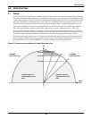
During normal UPS operations, short-term overload current demand from the bypass source may
reach 10 times the UPS output current rating. This overload current demand may be caused by the
magnetizing inrush current of one or more downstream transformers (i.e., PDUs—Power Distribution
Units) or faults on downstream branch circuits. The instantaneous trip point(s) of the upstream
bypass feeder breaker(s) must be set to support these temporary overloads. The magnitude of short-
term overload bypass current demand is typically six to eight times the UPS current rating, but must
be determined by analysis on a per-site basis. This analysis, generally known as an End-to-End Fault
Coordination Study, must be done by a Registered Professional Engineer experienced in this activity
and familiar with local codes and related requirements.
Liebert strongly recommends periodic inspections of the bypass feeder breaker instantaneous trip set-
tings, as well as the module input (rectifier) feeder breaker trip settings, to ensure that they are cor-
rect. For a variety of reasons, although typically during circuit breaker maintenance procedures by
others, trip settings have been known to be inadvertently left improperly set. Correct trip setting of
these circuit breakers is most important to achieving high-availability from your Liebert UPS system.
For further information regarding proper trip settings for your feeder breakers, call 1-800-LIEBERT.
Table 16 Recommended test equipment and tools
Qty Test Equipment Manufacturer Model or Type
1 Oscilloscope Tektronix, H-P or Fluke DC to 50 MHz
2 Voltage Probes Tektronix, H-P or Fluke 10X, with 10 ft. cable
2 Voltage Probes Tektronix, H-P or Fluke 100X, with 10 ft. cable
1 Digital Multi-meter Fluke 87, with test leads
1 Tool Kit N/A Standard electrical contractor tools
NOTE
The instantaneous trip setting of the breaker feeding the UPS bypass input should be high
enough to accommodate short-duration overloads. The bypass static switch power path inside
the UPS can draw up to 10 times the system’s rated current for up to three cycles.
NOTE
While Liebert can provide typical guidelines, the responsibility for the proper breaker trip
settings outside the Liebert-manufactured UPS equipment resides with the owner. Contact
Liebert Global Services at 1-800-LIEBERT for further details.


