Operation
72
Remote Monitor Panel
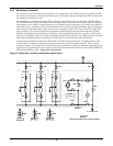
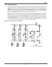
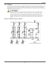
The Liebert Remote Monitor Panel provides an LED indication of the following conditions:
• Load On UPS
• Load On Bypass
• Battery Discharge
• Low Battery Warning
• Overload
• Ambient Overtemp
• System Summary Alarm
• New Alarm
This information is also available for customer use through a set of contacts on a separate terminal
board.
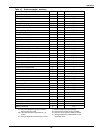
Alarm messages that activate the System Summary Alarm are listed in Table 6 and Table 7.
The Remote Monitor Panel housing is a NEMA Type 1 enclosure, available for either surface-mount
or flush-mount installations.
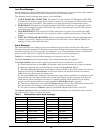
Separate / Simultaneous Outputs
The RS-232 interface can support a modem plus either a local terminal or a local monitor. The
SiteScan port can support either SiteScan or SNMP communications. Whatever communication
options are installed in the Liebert Series 610 UPS can all be used simultaneously.
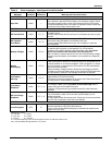
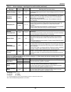
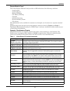
Table 11 Liebert Series 610 terminal commands
Key(s) Function
A, return
AN (N=1 to 6), return
Displays Present Status Report screen. NOTE: For all three report screens, a numeral 1
through 6 in place of N will access an individual UPS module. If no numeral is entered,
you will get a report from the SCC.
^B (control-B), return
^BN (N=1 to 6) return
Displays Event History Report screen, starting with the most recent frame and then
scrolling back through earlier frames.
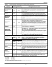
C, return
^CN (N=1 to 6), return
Displays History Status Report screen starting with the most recent frame and then
scrolling back through the earlier frames.
F (no return)
Freezes data output. This stops the data scrolling on the monitor to allow closer study or
a printout. This is a toggle switch command. Press the F key again to resume data
scrolling.
G, return
Resets (unfreezes and clears) the History Status Report memory buffer. This erases the
alarm messages and meter indications that were stored immediately before and after a
significant system fault. NOTE: Do not reset the History Status Report memory buffer
until operation and maintenance personnel have reviewed it as a troubleshooting tool.
Q (no return)
The data output stops (quits). The UPS communication system remains on stand-by,
ready to receive the next communication command. NOTE: To return to the beginning of
the Event History or History Status Report, press Q, then request your desired report
again.
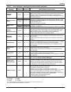
d mm/dd/yy, return
This entry sets the date (month/day/year) in the UPS system clock. You must include the
slash (/) as you key in the date. Note that the d command must be lower case.
t hh:mm:ss, return
This entry sets the time (hour:minute:second) in the UPS system clock. You must include
the colon (:) as you key in the time. Note that the t command must be lower case.
H, return
Prompts the UPS system to hang up its modem (only applicable to the modem
communications port).
I, return Display Battery Cycle Monitor information for 0-30 second discharge events.
J, return Display Battery Cycle Monitor information for 31-90 second discharge events.
K, return Display Battery Cycle Monitor information for 91-240 second discharge events.
L, return Display Battery Cycle Monitor information for over 240 second discharge events.
M, return Display Status Summary screen of battery discharge events.
N, return
Show detail information on all battery discharge events in order of occurrence
(last in, first out).
backspace Moves cursor left to cancel previous entry or command.


