Operation
51
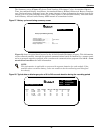
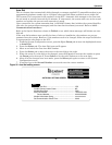
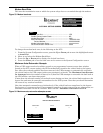
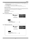
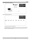
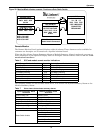
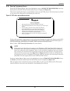
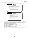
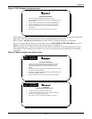
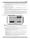
Figure 39 Monitor/Mimic display example: Continuous Duty Static Switch
Remote Monitor
The Remote Monitor Panel (optional) displays eight (8) alarms. These alarms are also available for
customer use through a set of contacts on a separate terminal board.
When the New Alarm, System Summary Alarm or Module Summary Alarm is activated, you can get
more information at the Operator Display Panel or through a remote terminal. Refer to 3.2.15 - Com-
munication Interfaces.
The following alarms, as well as those listed above, will activate the System Summary Alarm or the
Module Summary Alarm.
Table 6 SCC and module remote monitor indications
SCC Remote Monitor Indications Channel Module Remote Monitor Indications
Load On UPS CH1 Output CB Open
Load On Bypass CH2 Battery CB Open
Battery Discharging CH3 Battery Discharging
Low Battery Warning CH4 Low Battery Warning
Overload CH5 Control Failure
Ambient Overtemp CH6 Ambient Overtemp
System Summary Alarm CH7 Module Summary Alarm
New Alarm CH8 New Alarm
Table 7 Other alarms that activate summary alarms
System Summary Alarm
Activation
Module Summary Alarm
Activation
Control Power Fail Blower Failed
Emergency Off Control Power Fail
Module Summary Alarm DC Capacitor Fuse Blown
Output Over/Under Frequency DC Ground Fault
Output Overvoltage DC Overvoltage Shutdown
Output undervoltage Emergency Off
Overload Transfer Equipment Overtemperature
Static Switch Unable
Inverter Fault
Low Battery Shutdown
Overload
Overload Shutdown
Rectifier Fuse Blown
Reverse Power
BYPASS INPUT
∅A-B ∅B-C ∅C-A
480V 480V 480V
60.0Hz
UPS INPUT PWR
∅A-B ∅B-C ∅C-A
480V 480V 480V
UPS RATINGS
SCCB 1600
OUTPUT VOLTAGE
∅A-B ∅B-C ∅C-A
480V 480V 480V
60.0Hz
LOAD
627 KVA / 502 KW
∅A ∅B ∅C
755V 755V 755V
3 OF 3 MODULES
CONNECTED
REDUNDANT
MOD 1 ON LINE
MOD 2 ON LINE
MOD 3 ON LINE
CDSS
OK to Transfer
Static Switch Connected


