Theory of Operation
14
2.2.3 Battery Charging Circuit
The UPS module charging circuit is capable of recharging the battery plant to 95% of full capacity
within 10 times the discharge time. Recharging the last 5% takes longer because of characteristics
inherent in the battery. DC ripple voltage is limited to less than 0.5% RMS to preserve battery life
during long-term float charging while the UPS system is operating on utility source power.
Multiple UPS module rectifier/chargers can share a common battery plant, if that configuration is
preferred for your application.
Operation After Discharge
When commercial power is interrupted, the battery continues to supply DC power to the inverter
without interruption to the critical load. If the AC source power is restored before the battery has
fully discharged, the rectifier automatically restarts and resumes carrying the inverter and battery
recharge load requirements.
Operation After End-of-Discharge
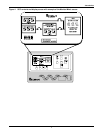
The battery time screen displayed on the control panel enables you to estimate when battery shut-
down will occur. If the battery plant discharges to the shutdown point during an outage, the UPS
automatically disconnects the load, the AC input and the battery. After AC input power is restored,
the rectifier can be manually restarted by the user.
Battery Disconnect
The external module battery disconnect (MBD) circuit breaker is used to isolate the UPS module from
the battery during maintenance and to automatically disconnect the battery from the inverter at the
end of battery discharge. The MBD circuit breaker can be opened or tripped automatically, from the
control panel or manually. It must be closed manually.
Battery Charge Current Limiting
The battery recharge current, after a battery discharge, is limited to between 1 and 25% (adjustable)
of the full load discharge current. An additional (optional) charge-limiting circuit can be activated by
external dry contact closure (field supplied) for use when operating on a back-up generator. These two
levels of control regulate the amount of current that flows from the power source to the battery while
the battery is recharging.
The battery charge current limit is factory-set at 10% for normal operation and at 1% for alternate
power source recharge operation.
Battery Equalize Charge Circuit
The battery equalize charge feature can be manually initiated or it can be programmed to operate
automatically. Either can be selected from the battery equalize screen displayed on the control panel.
The battery equalizing charge circuit increases the rectifier/charger output voltage to charge the bat-
tery any time there is a power outage of 30 seconds or longer. The equalizing voltage is slightly higher
than the float voltage. Equalize charging is primarily used in flooded battery systems to boost individ-
ual cells that are at a low state of charge, per the battery manufacturer's specification and recommen-
dations.
NOTE
Do not use equalize charging with valve-regulated lead-acid batteries.
Consult the battery manufacturer’s manual, available on the manufacturer’s Web site, for
specific information about equalize charging.


