


Managing the Switch
VLAN Configuration 3-3
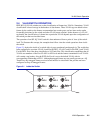
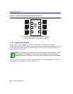
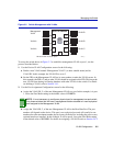
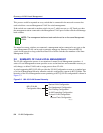
Figure 3-2 Switch Management with VLANs
To set up the switch shown in Figure 3-2 to establish a management VLAN on port 1, use the
process described below:
1. Use the Device VLAN Configuration screen for the following:
a. Define a new VLAN named “Management VLAN” (or other suitable name) and its
VLAN ID. In this example, the VLAN ID is set to 2.
b. Set the FID so the Management VLAN has its own number to make the VLAN secure. In
this example, the FID is 3 and no other VLAN should be assigned to this FID. This keeps the
new VLAN from sharing its filtering database with other VLANs in the switch. For details
on defining a VLAN, refer to Section 3.4.1.
2. Use the Port Assignment Configuration screen for the following:
a. Assign the VLAN ID, 2, of the new Management VLAN to a port. In this example, it is port
1. Leave the Port Mode setting in the default value of HYBRID.
b. Assign the VLAN ID, 2, of the new Management VLAN to the Host Data Port. The port
number will depend on the device. This port is not a physical port and will usually be one
number above the maximum number physical ports on the device, including the ports on any
optional interfaces installed. In this example, it will be port 8. Leave the Port Mode setting
in the default value of HYBRID. For details on assigning a VLAN ID, refer to Section 3.4.2.
NOTE: It is not necessary to configure a physical port for management on each switch.
Only those switches that will have a management station attached to it need a physical
port assigned to the Management VLAN.
1
3 6
2
4
5
802.1Q Switch
25992_15
VLAN A
VLAN B
VLAN B
VLAN C
Management
VLAN
VLAN A
7
Host
Data
Port
Set as an 802.1Q Trunk port.