


Example 3, 1D Trunk Connection to 802.1Q VLAN Network
4-12 Examples
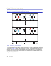
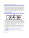
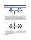
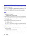
Figure 4-8 Bridge 1 Broadcasts Frames
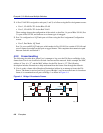
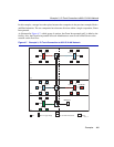
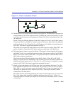
3. Switch 2 receives the tagged Red VLAN frame on Port 2, as shown in Figure 4-9. The VLAN
Tag in the frame is maintained, classifying the frame as belonging to the Red VLAN. The switch
forwards the broadcast frame out all the eligible ports, Ports 3 and 4. Switch 2 simultaneously
updates its Source Address Table for FID 1 to reflect the location of User B (Port 2).
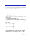
The frame forwarded out Port 3 has its VLAN Tag stripped before transmission, and it is passed
to Bridge 4 as a normal broadcast frame. The frame that is transmitted out Port 4, the 1Q Trunk,
retains its VLAN tag.
Figure 4-9 Switch 2 Forwards to 1Q Trunk
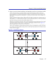
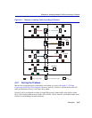
4. When Switch 1 receives the tagged broadcast frame, it also examines the tag and classifies the
frame as belonging to the Red VLAN. This broadcast frame is then sent to all ports eligible to
receive Red VLAN frames. In this case only the 1D trunk, Port 3, is eligible, as it is considered
a member of all VLANs for forwarding purposes. The VLAN Tag is stripped from the frame and
the frame is transmitted out Port 3 as shown in Figure 4-10. The Source Address Table, FID 1
for Switch 1 is updated to contain User B.
Floor 4
1
Bridge 1 Bridge 2
Red VLAN
Red VLAN
Blue VLAN
Blue VLAN
User B
2
4
3
4
2263_18
4
Floor 2
Floor 3
Bridge 3
Bridge 4
Red VLAN
Red VLAN
Blue VLAN
Blue VLAN
File Server
2
1
2
3
2263_19