


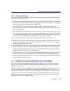
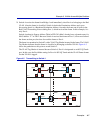
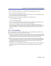
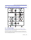

Example 3, 1D Trunk Connection to 802.1Q VLAN Network
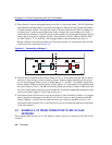
Examples 4-11
3. A Port VLAN ID is assigned to Port 1 using the Port Assignment screen, as follows:
• Port 1, VLAN ID: 224 for the Green VLAN
This setting changes the configuration of the switch, so that Port 1 is part of the Green VLAN
and is set to transmit a frame type of untagged.
4. The port mode of Ports 2 and 3 are set using the Port Assignment screen:
• Port 2, Port Mode: 1Q Trunk
• Port 3, Port Mode: 1D Trunk
Port 2 is set as an 802.1Q Trunk port, which makes the port eligible to transmit frames of all
VLANs, and sets all frames forwarded out this port as tagged frames.
Port 3 is set as a 1D Trunk port, where frames classified as belonging to any VLAN are
forwarded untagged, and received frames are classified as belonging to the Default VLAN. This
allows the Mail Server to send/receive mail traffic to/from all VLAN users on the network
backbone,
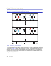
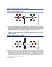
4.3.2 Frame Handling
The following describes how, when User B attempts to contact the Mail Server on Switch 1, the
frames are classified on Switch 4 and traverse the network.
1. User B sends a broadcast frame in an attempt to contact the Mail Server. The frame enters Bridge
1 and, being a broadcast, is forwarded to all ports. Bridge 1 learns User B’s MAC address from
the Source Address field of the frame and adds it to its Source Address Table in FID 1.
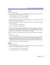
2. Switch 4 receives the frame and classifies this new untagged frame as belonging to the Red
VLAN. Since the frame is a broadcast, it is forwarded to any ports that are classified as eligible
to receive Red VLAN frames. Switch 4 also updates its Source Address Table for FID 1,
identifying User B as being located out Port 1.
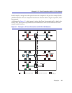
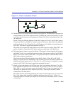
On Switch 4, the only port eligible to receive Red VLAN frames is Port 4, the 1Q Trunk. The
frame is forwarded out Port 4 with the Red VLAN Tag header being added, as shown in
Figure 4-8.