


DFE Modules
Enterasys Matrix DFE-Gold Series PoE Module Hardware Installation Guide 1-3
DFE Modules
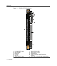
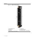
Thissectionprovidesanoverviewofthe4G4285‐49(Figure 1‐1)and4G4205‐72
(Figure 1‐2).ForinformationabouttheDFEmodulefeaturesandhowtoconfigurethem,
refertotheEnterasysMatrixDFE‐GoldSeriesConfigurationGuide.
4G4285-49
The4G4285‐49has48,10BASE‐T/100BASE‐TX/1000BASE‐T,PoE‐compliantportsthatare
accessedthroughthefixedfrontpanelRJ45connectors.Thereisalsoanoptionslotforan
networkexpansionmodule(NEM).TheDFEmodulecanbeinstalledinaMatrix E7,
Matrix N3,Matrix N5,orMatrix N7chassis.(SeeFigure 1‐1
onpage 1‐4.)
Eachofthefixedfrontpanelportscanoperateineitherhalf‐duplexorfull‐duplexmode
ofoperation.Theduplexmodecanbedeterminedbyeitherauto‐negotiationormanual
configuration.
TheDFEmoduleportscanbeconfiguredtoprovideahighlevelofsecurity,controltraffic
bylimitingtherateoftrafficacceptedintothemoduleandprioritizingtraffictoexpedite
theflowofhigherprioritytrafficthroughthe module.Foracompletelistofcapabilities,
refertotheEnterasysMatrixDFE‐GoldSeriesConfigurationGuide.
TheDFEmodulereceivespowerandbackplaneconnectivitywhenit
isinsertedintothe
Matrix E7,Matrix N7,Matrix N5,orMatrix N3chassis.ThepowertosupporttheDFE
moduleconnectionsto802.3afPoE‐compliant48VdcPDs(powereddevices)canbefrom
thebackplaneofaMatrix N5chassisorfromanoptionalexternalMatrixN‐POEPower
System.
TheMatrixN‐POEPower
Systemcanprovide48Vdctosupportuptoeight
PoE‐compliantDFEmodules.TheconnectionfromtheN‐POEPowerSystemisbywayof
the48Vdc~20AMaximum,optionalPowerInputconnectoronthefrontpanelofthe
DFEmodule.
Note: Only an N-POE Power System can be connected to the 48 Vdc ~ 20 A Maximum
Optional Power Input connector of a series PoE-compliant DFE module such as the
4G4285-49.