


Preparing to Install Module into Matrix E7 or N7 Chassis
3-8 Installation
ToinstallaDFEmoduleintoaMatrix E7or Matrix N7 chassis,proceedasfollowsto
preparethemoduleforinstallation.
1. Removetheblankpanelcoveringtheslotinwhichthemodulewillbeinstalled.All
otherslotsmustremaincoveredtoensureproperairflowforcooling.(Savetheblank
plateintheeventyouneedtoremovethemodule.)
2. Removethemodule
fromtheshippingbox.(Savetheboxandpackingmaterialsin
theeventthemoduleneedstobereshipped.)
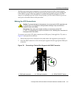
3. Locatetheantistaticwriststrapshippedwiththechassis.Attachtheantistaticwrist
straptoyourwristandplugthecablefromtheantistaticwriststrapintotheESD
groundingreceptacleat
theupperrightcornerofthechassis.
4. Removethemodulefromtheplasticbag.(Savethebagintheeventthemodulemust
bereshipped.)ObserveallprecautionstopreventdamagefromElectrostatic
Discharge(ESD).
5. Examinethemodulefordamage.Ifanydamageexists,DONOTinstallthemodule.
Immediatelycontact
EnterasysNetworks.Referto“GettingHelp”onpage xviii.
6. Toinstalla4G4285‐49or4G4205‐72intoaMatrix E7
or Matrix N7,proceedto
“InstallingtheDFEModulesintoaMatrix E7orN7Chassis”onpage 3‐8.For
Matrix N3
orMatrix N5,referto“InstallingtheDFEModulesintoMatrixN3or
Matrix N5Chassis”onpage 3‐11.
Installing the DFE Modules into a Matrix E7 or N7 Chassis
BeforeinstallingamoduleintoaMatrix E7orN7chassis,makesurethatyoureferto
instructionin“Preparation”onpage 3‐6.
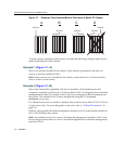
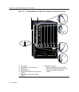
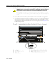
Toinstallthemodule,refertoFigure 3‐2andproceedasfollows:
1. Preparethechassisasdescribedin“InstallingtheDFEModuleintoaChassis”on
page 3‐5.
2. Locatethechassiscardguidesthatlineupwiththeslotnumberinwhichthemodule
willbeinstalled.Makesurethemodulelockingleversareintheopenposition(top
andbottom).
Caution: To prevent damaging the backplane connectors in the following step, take care
that the module slides in straight and properly engages the backplane connectors.
Ensure that the top lever lines up with the desired slot number located on the front panel
of the chassis. Refer to Figure 3-2.
Precaución: Para evitar que se dañen los conectores del panel posterior en el siguiente
paso, intente deslizar el módulo en forma recta y verifique que se enganche
correctamente en los conectores de panel posterior.
Asegúrese de que la palanca superior esté alineada con respecto al número de ranura
correspondiente ubicado en el panel frontal del chasis. Consulte en Figure 3-2.