


Preparing to Install Module into Matrix E7 or N7 Chassis
3-10 Installation
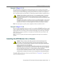
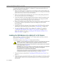
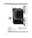
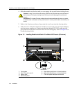
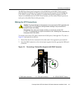
Figure 3-2 Installing Module into Matrix E7 or Matrix N7 Chassis (E7 shown)
1 Card guides 7 Backplane connectors
2 Slot number 6 (Left-most slot is 1) • Top two connectors (power and FTM2
3 Module card • Bottom two connectors (power and FTM1)
4 Metal back panel (no bottom connectors in Matrix N7
5 Upper/lower locking tabs (in proper open
position)
chassis
)
6 Upper/lower locking tab (in closed
position)
1
Å
Å
SERIES
E7
45
6
7
23
Á
50/60Hz
LINE
100-125V~12A
200-240V~6A
50/60Hz
LINE
100-125V~12A
200-240V~6A
ACON
1
0
POWER FAN
PS1
50/60Hz
LINE
100-125V~12A
200-240V~6A
50/60Hz
LINE
100-125V~12A
200-240V~6A
ACON
1
0
POWER FAN
PS2
Æ
Ã
Â
À
COM
OFFLINE / RESET
CPU
MGMT
GROUP
GROUP
SELECT
GROUP 1 GROUP 2
GROUP 3
1X
6X
7X
12X
13X
18X
19X
24X
1 2 3
4G4205-72
Gb ENET
DFE
Ä
Ä