


Connecting to the Network
3-16 Installation
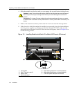
3. VerifythatalinkexistsbycheckingthattheportRX(Receive)LEDisON(flashing
amber,blinkinggreen,orsolidgreen).IftheRXLEDisOFFandtheTX(Transmit)
LEDisnotblinkingamber,performthefollowingstepsuntilitison:
a. Toviewthereceiveandtransmit
activityonagroupofsegments,pressthe
GROUPSELECTbuttonforlessthanonesecond(seeFigure 3‐4)tosteptothe
groupofinterest(Groups1through4).
b. EachtimetheGROUPSELECTbuttonispressedforlessthatonesecond,the
GROUPLEDlightsupinsequence,
indicatingwhichGroupisselected.The
receiveandtransmitactivityforthatgroupofsegmentsisthenindicatedbythe
RXandTXLEDsforeachsegment.
c. VerifythatthecablingbeingusedisCategory5UTPwithanimpedancebetween
85and111 ohms.Iftheportistooperateat
100 Mbps,category 5cablingmustbe
used.
d. Verifythatthedeviceattheotherendofthetwistedpairsegmentison,and
properlyconnectedtothesegment.
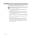
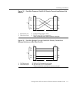
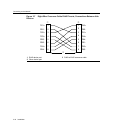
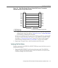
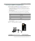
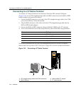
e. VerifythattheRJ45connectorsonthetwistedpairsegmenthavetheproper
pinoutsandcheckthecableforcontinuity.Typically ,acrossovercableis
used
betweenhubdevices.Astraight‐throughcableisusedtoconnectbetween
switchesorhubdevicesandanenduser(computer).RefertoFigure 3‐5and
Figure 3‐6forfour‐wireRJ45connections.RefertoFigure 3‐7andFigure 3‐8for
eight‐wireRJ45connections.
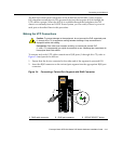
Note: If the RX and TX LEDs of a port do not indicate a link and the end-point device is a
PD, you may have a port without 48 Vdc to operate the PD. To check the PoE Port Status,
refer to “Verifying PoE Port Status” on page 3-19.