


Gaining Access to Memory Modules
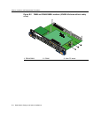
B-8 Mode Switch Settings and Option Installations
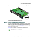
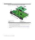
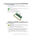
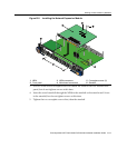
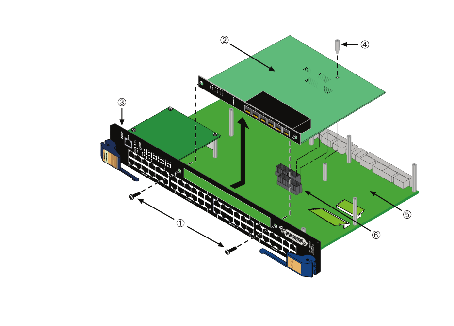
Figure B-4 Removing the Network Expansion Module (NEM)
2. RemovethetwoscrewsfasteningtheNEMtotheDFE modulefrontpaneland
removethestandofffasteningtheNEMtothemainboard.Savethetwoscrewsand
standoffforlaterusetoreinstalltheNEM.
3. LiftandremovetheNEMoffthetwomainPCboardconnectors.Nowyouhave
accesstotheDIMM.ToreplacetheDIMM,proceedto“RemovingtheDIMM”on
page B‐10.
1 Coverplate screws (2) 4 Standoff
2 NEM 5 Main PC board
3 DFE module front panel 6 Main board connectors