


Preparing to Install Module into Matrix E7 or N7 Chassis
3-12 Installation
4. Slidethemoduleintotheslotuntilyoucanengagethetopandbottomlockinglevers.
5. RefertotheCautionnoteabove,thenrotatethetwoleversintotheclosedposition.
6. Ifthechassisinwhichthemoduleisinstalledwaspowereddownfortheinstallation,
turnthepowersupplieson.Check
toseethatthemoduleCPULEDsettlesatsolid
greenafterafewminutes.IftheLEDdoesnotturnsolidgreen,refertoChapter 4for
troubleshootingdetails.
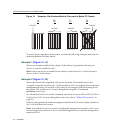
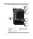
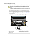
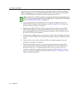
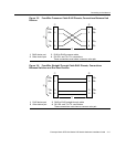
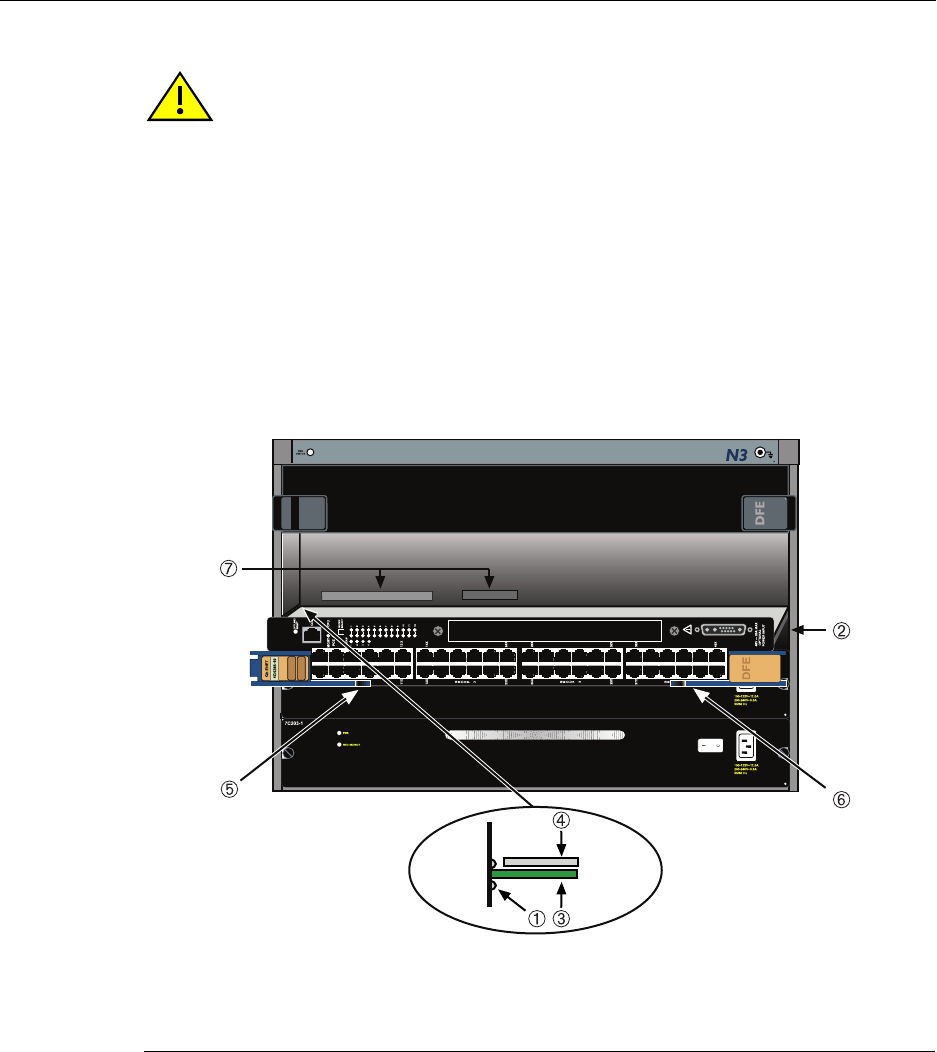
Figure 3-3 Installing Module into Matrix N3 or Matrix N5 Chassis (N3 shown)
Caution: In step 5, do not force the locking levers to the point that they touch the face of
the front panel. Forcing the locking levers to this point could damage the module and
chassis.
Precaución: En el paso 5, tenga cuidado de no llevar las palancas de cierre a un punto
en donde estén en contacto con el panel frontal. Si lo hace, podría dañar el módulo y/o el
chasis.
1 Card guides 5 Upper locking tab (shown in closed position)
2 Slot 1 (Top slot is slot 3.) 6 Lower locking tab (shown in closed position)
3 Module card 7 FTM2 and power backplane connectors
4 Metal back panel