


INTERFACE MODEL 9840 VER 6.0.2
APPENDIX B -- CABLES AND CONNECTORS
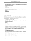
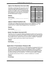
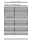
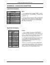
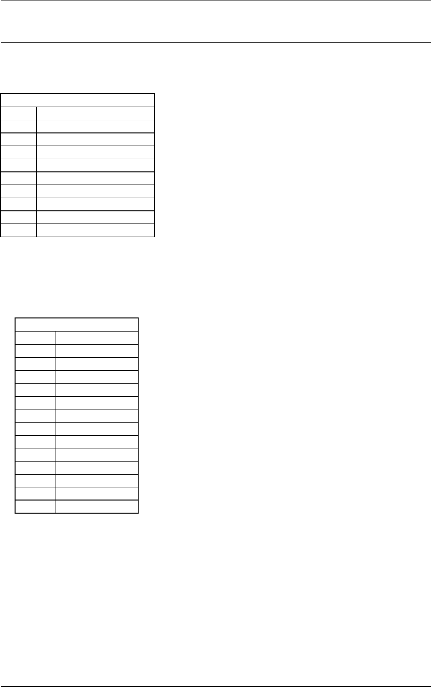
Load Cell Connectors
Notes:
DB9 Female
Pin Signal
1 EXCITE - HI
2 SENSE - HI
1
3 CELL OUTPUT - HI
4 CELL OUTPUT - LO
5 SENSE - LO
1
6 EXCITE - LO
7 AUTO ID - A
8 AUTO ID - B
9 CHASSIS GND
1. If the sense lines are not used, SENSE - HI must
be tied to EXCITE - HI and SENSE - LO must be tied
to EXCITE - LO.
2. Incorrect wiring of these ports can cause damage
to the internal circuitry of the unit. Please contact
Interface if you have questions or need assistance
with these configurations.
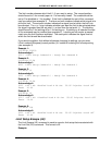
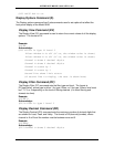
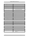
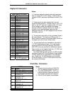
Serial Port Connector
Notes:
DB 15 Male
Pin Signal
1 TXD
2 RXD
3 No Connect
4 SERIAL GND
5 TXD+ (Printer)
6 TXD- (Printer)
7 RXD- (RS485)
8 RXD+ (RS485)
9 No Connect
10 SERIAL GND
11-13 No Connect
14 TXD+ (RS485)
15 TXD- (RS485)
1. Pins 1 through 4 are used for RS232 ASCII
command set communications. Use 8 data bits, no
parity, 1 stop, and set the baud rate using the Com
baud rate entry on the System Options menu.
2. The printer uses RS422 differential signaling on
pins 5, 6 and 10. Baud rate for the printer is
selectable using the Printer Baud entry on the
System Options menu.
3. Pins 7, 8, 14 and 15 are used for RS485 ASCII
command set communications. Use 8 data bits, no
parity, 1 stop, and set the baud rate using the Com
baud rate entry on the System Options menu.
MODEL 9840 PG 55 PUB. 2856-16