


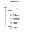
INTERFACE MODEL 9840 VER 6.0.2
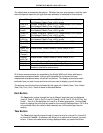
# Message Meaning
1 Interface X.Y.Z This is the version number.
2 Serial # 12345
Option # 114236
This is the serial number.
This is the option number.
3 Last ID A LD90437
Last ID B TQ12030
The serial number of the load cell on Ch A.
The serial number of the torque cell on Ch B
4 Ch A Max 4.00Lb
Ch B Max 4.00LbI
Maximum rated load of the sensor on channel A.
Maximum rated torque of the sensor on channel B.
5 Ch A Cal 4.00000 mVv
Ch B Cal 4.00000 mVv
The mV/V constant used with the load cell on channel A.
The mV/V constant used with the torque cell on channel
B.
Note: If either of these sensors was calibrated by 5 –Point
Mass, then 4 mV/V constants will be displayed here.
6 Ch A Exc 5.00 Volt
Ch B Exc 10.00 Volt
Excitation voltage used with the load cell on channel A.
Excitation voltage used with the torque cell on channel B.
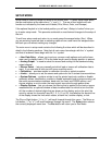
Each of these messages will be displayed for about 3 seconds. After that the front display
will start showing the current readings from the sensor.
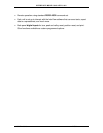
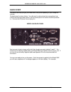
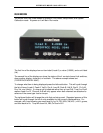
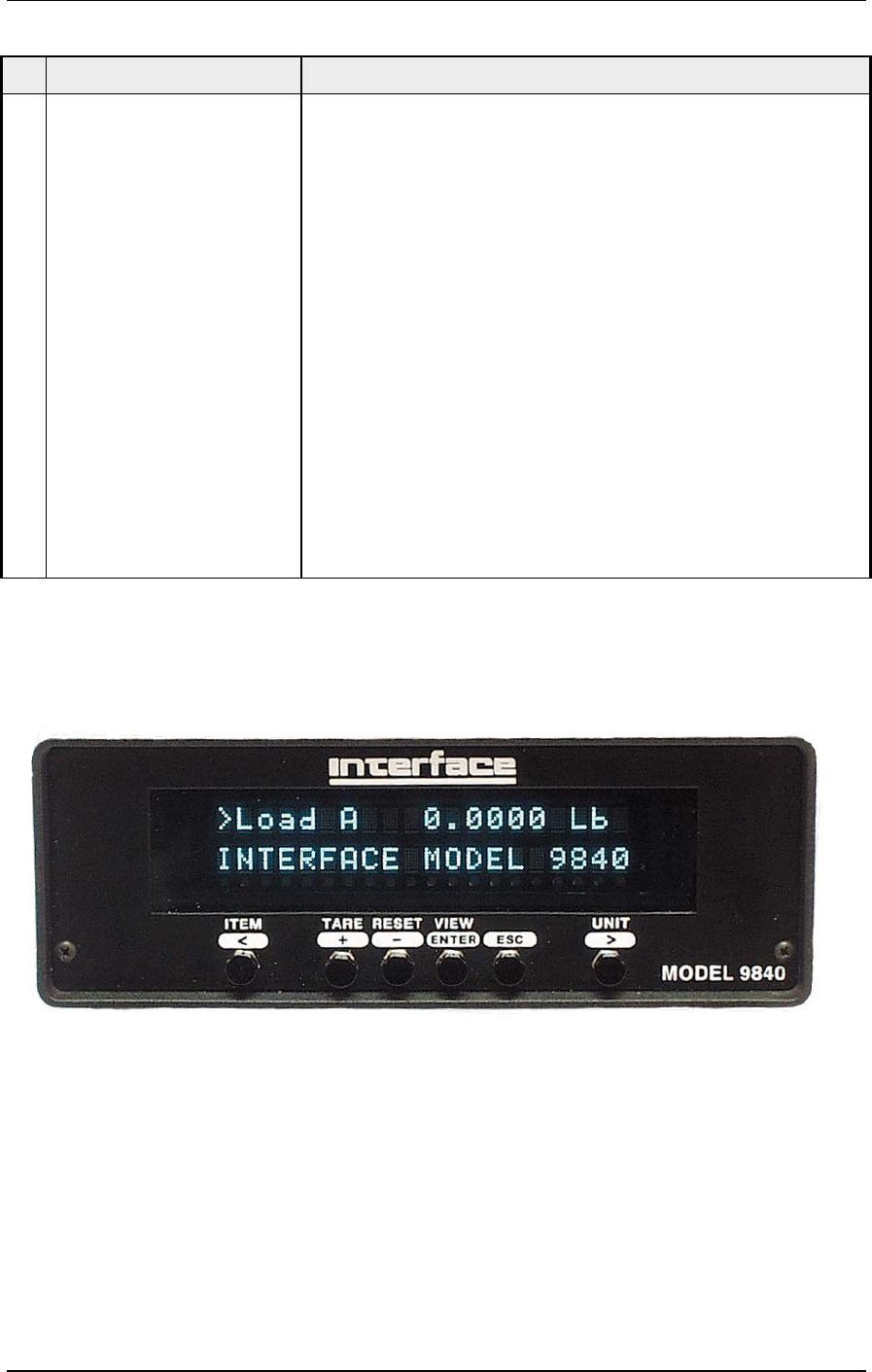
MODEL 9840 FRONT PANEL
The example above shows that Load A is 0.0000 Lb. The second line of the display
shows text.
To change what item is being displayed press the leftmost button. This will cycle through
the list of items (load A, peak A, valley A, gross A, load B, peak B, valley B, gross B,
channel A+B, pos, velocity, lim). If a torque cell is loaded on either channel, the display
will show torq rather than load for the appropriate channel. Channel A+B will only appear
when both channels are attached to sensors of the same type: load or torque.
MODEL 9840 PG 7 PUB. 2856-16