


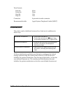
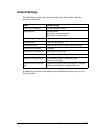

Interface Specifications
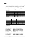
Parallel Interface
Data format: 8-bit parallel, IEEE P1284 compatible mode
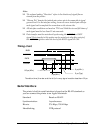
Synchronization:
STROBE pulse
Handshake timing: BUSY and
ACKNLG signals
Signal level: TTL compatible
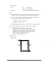
Connector: 36-pin, Centronics compatible connector
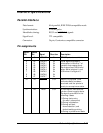
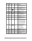
Pin assignments
Signal
Pin
Return
Pin Signal Direction Description
119
STROBE IN STROBE
pulse to read data.
2
3
4
5
6
7
8
9
20
21
22
23
24
25
26
27
DATA 0
DATA 1
DATA 2
DATA 3
DATA 4
DATA 5
DATA 6
DATA 7
IN
IN
IN
IN
IN
IN
IN
IN
These signals represent
information in bits 0 to 7 of
parallel data respectively.
Each signal is at HIGH level
when data is logical 1 and
LOW when it is logical 0.
10 28
ACKNLG OUT About a 5-µs pulse. LOW
indicates data has been
received and the printer is
ready to accept more data.
11 29 BUSY OUT A HIGH signal indicates the
printer cannot receive data.
The signal goes HIGH in the
following cases:
1) During data entry
(for each character)
2) During initialization
3) During self test,
demonstration, and
default-setting printing
4) During a printer-error state
Technical Specifications
A-9