


2-15
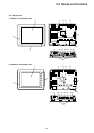
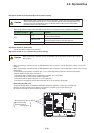
2-3 Names and Functions
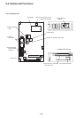
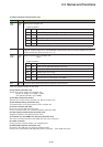
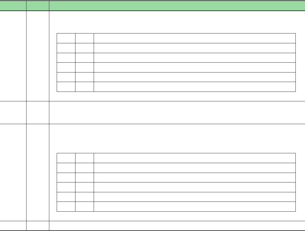
1) Status indication LED (Controller unit)
Symbol Color Descriptions
ONL
ERR
Green
Red
Status of the controller unit.
<Lights on pattern>
ONL ERR Status of controller unit
OFF OFF Power OFF, system resetting or initializing
Blinks - SX bus standing on
ON OFF Normally running
ON ON Nonfatal fault, at a running
OFF ON Fatal fault at a stop
UROM Green Lights on continuously when the CPU recognizes a user ROM card.
Lights on continuously when a user ROM card (compact flash card) is correctly installed in the CPU
module and the key switch is set to "3" or "4".
RUN
ALM
Green
Red
Status of system of the conntroller unit.
(Note)
<Lights on pattern>
RUN ALM Status of system
OFF OFF Power OFF or application program at a stop
ON OFF Normally running
ON ON Nonfatal fault, at a running
OFF ON Fatal fault, at a stop
Blinks - While the CPU is accessing the user ROM
BAT Orange Turned on when data backup battery dropped or disconnected.
Note: The system includes the own CPU.
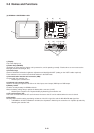
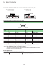
2) Key switch (Controller unit)
Selects the running mode of the controller unit.
1: STOP 2: TERM 3: U-TERM 4: RUN
* The shipment default is 3 (U-TERM).
3) CPU No. selection key switch
Sets the CPU number of the controller unit. Set the number to “0”.
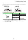
4) Data backup battery (Controller unit)
The battery backs up the retain memory of the contoller uint.
5) SX bus connector (IN, OUT)
Be sure to connect cable from OUT to IN.
For the connection cable, use a dedicated SX bus extension cable.
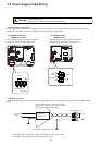
6) Power supply terminal block (Controller unit)
Supplies the power to the display unit (24 V DC).
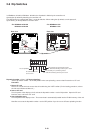
7) Connector for user ROM card (CF card) (Controller unit)
This is the connector where the User ROM card (CF card) is inserted.
8) Loader connector
For the personal computer loader, use a RS-232C port.
9) USB-miniB connector (Controller unit)
Connects to the USB port of a personal computer loader.
Please use a commercially sold USB cable (male A connector _ male miniB connector).