


Pressure Systems, Inc. 98RK-1 & 9816 User’s Manual©
Page 108 www.PressureSystems.com
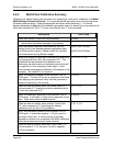
4.4.2 Multi-Point Calibration Summary
Following is a simple step-by-step procedure for executing a “multi-point” calibration of a Model
9816 Intelligent Pressure Scanner. It is assumed that all channels in the unit have the same
full-scale pressure range. Optional commands are shown within brackets [ ]. If it should
become necessary to abandon this calibration procedure once it is started, you may execute the
Abort sub-command [C 03] of ‘C’ at any time after the first ‘C’ sub-command.
Description TCP/IP Data
Insure that valves in RUN/CAL mode (default). [w1200]
… normal data acquisition assumed to be running
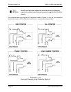
Place the module calibration manifolds into the CAL
position if this is the desired pressure application input.
The RUN position may be a better choice for modules
with transducers having different ranges.
[w0C01] for CAL pos.
[w0C00] for RUN pos.
Ready the module for multi-point calibration by executing
the Configure & Start (‘00’) sub-command of ‘C’. This
establishes all the channels to be affected, and
determines the total number of calibration points that will
be supplied (3 in this example) in later steps. It also
starts module averaging for calibration (64 samples in this
example). The linear fit (1) is required.
C 00 FFFF 3 1 64
Apply 1st calibration pressure to the module’s CAL or
RUN inputs. The zero (0.0) point is assumed in this case.
After applying zero pressure verify that this pressure is
measured correctly by the module.
[rFFFF0]
When the data are stable, enter the Collect Data (‘01’)
sub-command of ‘C’ specifying this first calibration point
(1) with zero pressure (0.0).
C 01 1 0.0
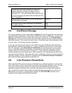
Apply 2nd calibration pressure to the module’s CAL or
RUN inputs. A full-scale (+5 psi) point is assumed in this
case. Verify that pressure reads correctly.
[rFFFF0]
When the data are stable, enter another Collect Data
(‘01’) sub-command of ‘C’ specifying this second
calibration point (2) with 5.0 psi pressure.
C 01 2 5.0
Apply 3rd calibration pressure to the module’s CAL or
RUN inputs. A mid-scale negative (-2.5 psi) point is
assumed in this case. A vacuum pump is normally
required to achieve such a pressure with 903x calibrators.
Verify that measured pressure reads correctly.
[rFFFF0]
When the data are stable, enter last Collect Data (‘01’)
sub-command of ‘C’ for this point (3) with a negative
(-2.5 psi) pressure.
C 01 3 -2.5