


Pressure Systems, Inc. 98RK-1 & 9816 User’s Manual©
Page 116 www.PressureSystems.com
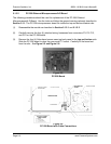
5.1.3.2 PC-299 Ethernet Microprocessor/A-D Board
The following procedures should be used for replacement of the PC-299 Ethernet
Microprocessor/A-D Board. Use the tools and follow the general warnings already described in
Section 5.1.1. The PC-299 microprocessor board fits inside the top and bottom bracket rails.
(1) Disassemble the module as described in Section 5.1.2.1 and 5.1.2.2.
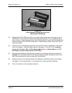
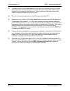
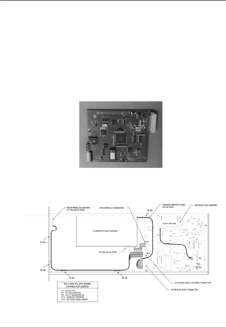
(2) Carefully remove the four (4) attached wiring harnesses from connectors P3, P5, P12,
and P13 on the PC-299 board.
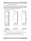
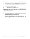
(3) Remove the four (4) Allen-head screws securing back panel to the top and bottom rails.
Slide the PC-299 board to clear the rear panel P-2 cutout. Carefully lift the board out
from the rails. See Figure 5.5 and Figure 5.6.
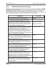
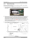
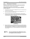
Figure 5.5
PC-299 Board
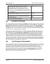
Figure 5.6
PC-299 Board with Cable Connections