


Pressure Systems, Inc. 98RK-1 & 9816 User’s Manual©
Page 26 www.PressureSystems.com
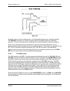
2.3.4.6 Calibration Manifold Position Detector Circuit
The transducer calibration manifold position detector circuit uses reflective infrared sensors to
sense the actual position of the manifold valve block. The block, located within the valve
assembly, is shifted to a desired position by pneumatic pistons positioned around the block.
Two reflective infrared sensors, which sense the position of the block by the reflection of the
sensor infrared beam from the block surface, are mounted into the assembly. If the block is in
front of the sensor, a low level logic signal is output by the sensor, indicating the presence of the
block. If the block is not in front of the sensor, the infrared beam is not reflected and the sensor
outputs a logic high signal.
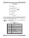
Outputs of these sensors are routed to the PC-299 microprocessor board and then to the CAL
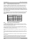
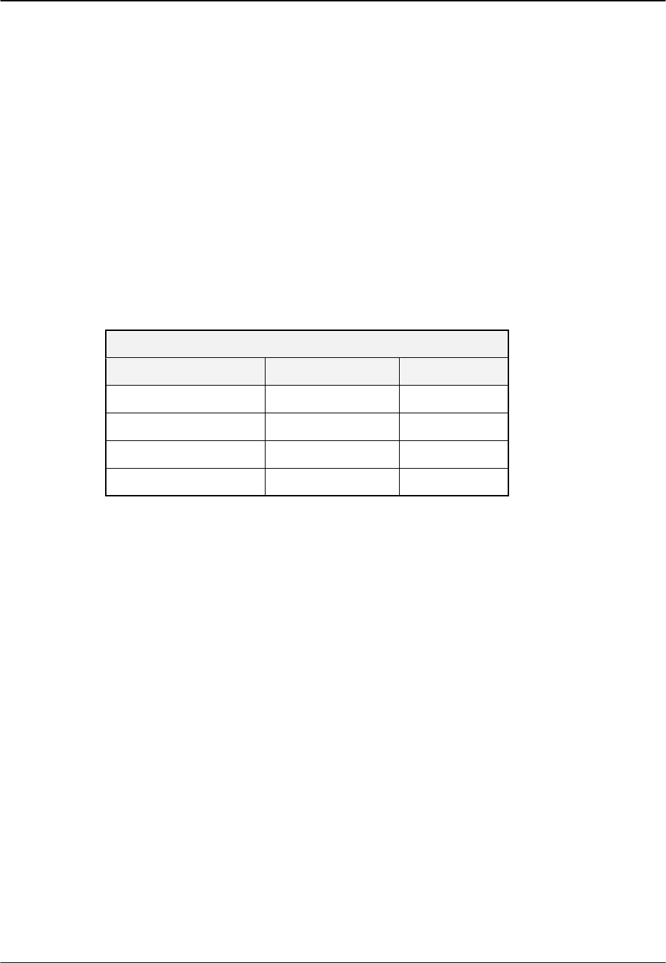
and purge (PRG) LEDs on the front of the module chassis. The following table shows the
position of the transducer calibration manifold assembly corresponding to front panel LED
illumination.
LED INDICATORS
VALVE POSITION CAL PRG
RUN OFF OFF
CAL ON OFF
PURGE ON ON
LEAK/CHARGE OFF ON
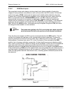
2.3.5 Cluster, Rack, and Slot Identification
The 98RK-1 Scanner Interface Rack can operate as a single unit, with one (1) to eight (8)
pressure scanners installed in each rack. Racks may also be grouped together as a cluster of
racks as part of a larger data acquisition system.
In order to physically identify individual scanners within a data acquisition system, a simple
addressing scheme is available. Individual scanners are identified by their Cluster, Rack, and
Slot (CRS) address, a three-digit hexadecimal number.
A cluster (the most significant address unit), is numbered 0-F (hex), for a total of 16 clusters of
racks.
A rack (the middle address digit), may be numbered 0-15, for a total of 16 racks. (NOTE: The
switch for setting the rack address is numbered in integers, but the address is returned in hex —
0-F.)
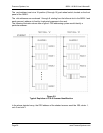
A slot (the least significant address unit), numbered 1 through 8, designates a particular 9816
pressure scanner.
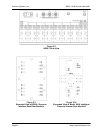
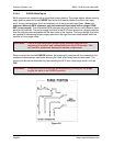
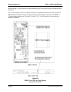
The diagram on the following page depicts the 98RK-1 Scanner Interface Rack front pullout
panel with switches identified for setting Cluster and Rack addresses. Cluster and Rack
addresses may be set at any number (user option) as long as it falls within the range of the