


Pressure Systems, Inc. 98RK-1 & 9816 User’s Manual©
Page 130 www.PressureSystems.com
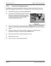
5.1.6.7 Solenoid Valve O-Ring Replacement
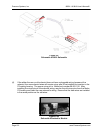
The rear panel quick disconnect (QDC) block (if your 98RK-1 Scanner Interface Rack is
equipped for rear-mounted tubing) may be removed as a complete unit (eight QDC blocks
attached to a non-removable eight-piece manifold) and may be re-installed as a complete unit or
each of the eight blocks may be re-installed individually. Each rear QDC consists of an “H”
block, tubed to an adapter plate, and a tubing plate. There are O-rings on the “H” block and the
tubing plate. If a leak is suspected in the rear panel quick disconnect (QDC) block.
(1) Remove eight (8) 10-24 x ½" stainless steel (ss) Phillips-head screws. One screw is
used to hold each of the eight (8) modules to its individual adapter plate.
(2) Remove four (4) 6-32 x ¼" stainless steel (ss) Phillips-head screws from the sides of the
rear panel QDC mounting plate, and three (3) 4-40 x d" anodized Allen-head screws from
the bottom of the rear panel QDC mounting plate.
(3) Remove the entire QDC assembly.
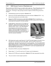
(4) Inspect the rear QDC (“H” block and tubing plate) O-rings and if any are suspect,
carefully remove with tweezers. (Do not scratch either the “H” block or the tubing plate,
as this may induce additional leaks.)
(5) Clean the O-ring cup with a lint-free applicator moistened with a cleaning fluid such as
acetone, alcohol, Freon, or any other substance that evaporates quickly and leaves very
little residue. Remove any excess cleaner with supply air (dry) as soon as possible. Do
not blow air directly into the holes of the surface since that could drive the fluid into the
scanner.
(6) Apply a very small amount of Krytox
®
fluorinated grease to the entire manifold (“H” block
and tubing plate), being careful not to allow any excess grease to cover any tubing port.
(7) Re-install the QDC assembly. It is extremely critical that each “H” block tubing assembly
be mated exactly to its adapter plate on the eight-piece manifold. For this procedure, it
may be prudent to disassemble each QDC from its mounting rack and individually re-
install it. To remove each QDC from its mounting rack, remove the four (4) 4-40 d" Allen-
head screws (one in each corner of the QDC).
(8) Mount the “H” block tubing assembly to its adapter plate on the eight-piece manifold and
secure with its 10-24 x ½" stainless steel Phillips-head screw. Assemble each of the
tubing blocks in this manner, and then re-connect them to the mounting plate with the
Allen-head screws.
(9) Re-connect the QDC mounting rack to the 98RK-1 chassis with the four (4) 6-32 x ¼"
stainless steel Phillips-head screws (at the ends) and the three (3) 4-40 x d" anodized
Allen-head screws.
(10) Test your scanner to ensure proper operation.