


Pressure Systems, Inc. 98RK-1 & 9816 User’s Manual©
Page 136 www.PressureSystems.com
Chapter 6
Troubleshooting Guide
6.1 98RK-1 Scanner Interface Rack and
Module Troubleshooting
6.1.1 Checking 98RK-1 Scanner Interface Rack Power-up
Sequence
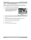
(1) Power to the 98RK-1 should first be verified. Since all internal and external modules are
powered by the 98RK-1 Scanner Interface Rack, make sure the rack is plugged into the
proper type of power receptacle.
(2) Turn the rack power switch ON. All tray front panel LEDs should illuminate briefly. Verify
the 98RK-1 front panel LED status, as described below.
● LEDs labeled “ Power Indicators” (four (4) LEDs, labeled +12, -12, +5, and +24)
should remain ON.
If these LEDs are not on, all other 98RK-1 LEDs as well as the individual module
LEDs will likely be off. Make sure the rack is plugged into a proper power
receptacle and check that the fuses on the PC-363 board (in the pull-out tray) are
. intact.
● Collision LED should remain OFF.
● Link LEDs (Local: 1-8; and Remote: 1-3 and Host) should remain ON or blinking
(for rack slots or remote connectors with attached or installed NetScanner
™
System products only). The color of the Link LED reflects the negogiated
interface speed: yellow for 10T, green for 100T, and blue for 1000T. These LEDs
indicate proper Ethernet connections.