


Pressure Systems, Inc. 98RK-1 & 9816 User’s Manual©
Page 132 www.PressureSystems.com
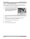
5.1.6.9 Supply Air and Purge Air Sensing Transducers
The pneumatic input manifold (pneumatic backplane) on the 98RK-1 Scanner Interface Rack
contains two (2) additional DH200 transducers to provide facility measurements for additional
diagnostic capabilities. The transducers read supply air pressure and purge air pressure.
Proper supply air is required to move the calibration valve to implement such functions as re-
zero or purge. Proper purge pressure is required to blow contaminants away from the module.
Without a sufficient amount of purge pressure, contaminants could migrate back into the
calibration valve assembly and cause catastrophic damage to the scanner. Pressures detected
by these transducers may be read through the NUSS application or through the TCP/IP
connection with an appropriate ‘r’ command. The pressures associated with these transducers
are read as channels 17 and 18 (of a sixteen (16) channel scanner) and are displayed before
the scanner channel pressures.
Following are procedures for replacing the supply air and purge air sensing transducers and/or
their associated O-rings on 98RK-1 racks.
(1) Make sure the 98RK-1 Scanner Interface Rack power switch is in the OFF position and
the unit is unplugged from electrical power. Make sure there is no pressure applied to
any of the input ports.
(2) Remove the eight (8) Phillips-head screws (front and side) holding the backplane panel in
place. Gently pull the panel out and allow it to rest on the power supply leads and the
ribbon cable connecting the rear panel to the back plane.
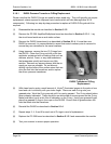
Note
As you are looking at the pneumatic backplane, the two
transducers are on the right side of the pneumatic input manifold;
the purge-sensing transducer is on the right and the supply-
sensing transducer is on the left.
(3) Remove the two grommets that cover the access holes in the top of the 98RK-1 chassis
(directly over each transducer). Note: it may be easier, with less opportunity to abrade
the chassis, to punch the grommets out from underneath, using your Allen-head or
Phillips-head screwdriver.
(4) Remove the 3/32" Allen-head screw from each of the transducers, being careful not to
drop the screw behind the manifold assembly. These screws attach to stand-offs and act
as stabilizers for the flex circuit.
(5) Unplug the eight-pin flex circuit from both DH200s (transducers). The flex circuit is a
single-piece unit that must be unplugged from both transducers.
(6) Remove the transducer by removing the 4-40 threaded stand-off screw and lifting the
transducer straight up from the mounting block. Make sure the two (2) O-rings remain
with the transducer as it is removed and the mounting block is clean and free of
contaminants. To replace the transducer O-rings, use the procedure as described in
Section 5.1.4. If the entire transducer is to be replaced, make sure to also replace the O-
rings. Additionally, ensure that the replaced transducer is the same pressure rating as
the old one.
Note
The pressure rating of the purge-sensing transducer is 750 psi and
the pressure rating of the supply-sensing transducer is 150 psi.