


Conditioned Power Center
19
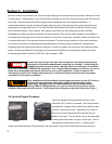
5.5.2 Programmable Circuit Breakers
Before beginning installation, check the tag on the circuit breaker. The power conditioner has been
manufactured and shipped according to the input voltage specified at the time the order was placed. If the input
voltage information shown on the tag does not match the voltage available at your site, check the tag to
determine the transformer primary configuration and circuit breaker type. If equipped with a programmable circuit
breaker and a transformer with a multiple voltage primary, it will be necessary to adjust the transformer’s primary
taps. Transformer primary tap connections are included in the specification sheet found in Section 10 of this
manual.
Breaker operating parameters such as input current, inrush characteristics, and time delay may all be
programmed to make it easier to adapt the power conditioner in the field to a full range of site installation
voltages. In order to reprogram the circuit breaker, it is necessary to gain access to the front of the breaker itself.
This is accomplished by removing the side panels as described previously in Sec. 5.3. Once the side panels
have been removed, proceed as follows:
1. The front bezel is attached to the frame of the power conditioner with screws on each side of the conditioner
frame. Remove the screws on each side of the front bezel, and remove the bezel from the power conditioner. (If
equipped with optional power management package or basic metering package, it will also be necessary to
unplug the wiring harness connecting the power management computer to the power conditioner before
removing the bezel. This is done by disconnecting at the Molex connector).
2. The front control panel is now accessible. It is hinged on the left side. Undo the screw on the right side of the
control panel and swing the control panel out to the left exposing the front of the breaker.
3. A hinged cover protects the breaker DIP switches. Raise the cover to gain access to the DIP switches.
Change DIP switch settings using the instructions included in the specifications sheet found in Section 10 of this
manual. Consult the manufacturer if you have any questions or difficulties.
5.6 Isolation Transformer
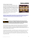
NOTE: CPC series power conditioners utilize a low-impedance isolation transformer. When first
energized, transformers of this kind typically exhibit a high "inrush" current that may approach 10-15
times the nominal rating. While inrush currents quickly decay to nominal, it is possible to experience
"nuisance" tripping of the source circuit breaker. If this occurs consult the manufacturer for options.
Section 5 - Installation