Conditioned Power Center
29
Section 7 - Options
activated by the closure of an interlock switch or EMO button, provides a DC voltage to the over-voltage shunt
trip coil of the input circuit breaker. In the standard EMO design, the DC voltage is derived via a full wave bridge
rectifier powered from a 24 volt AC tap on the main transformer secondary winding.
For SEMI S2-0200 approval, the EMO functions differently from the standard EMO. The SEMI S2-0200 EMO
operates as a normally closed (N.C.) circuit which provides a continuous DC voltage to an under-voltage shunt
trip coil in the input circuit breaker. Activating the EMO pushbutton or a panel interlock opens the safety circuit
and removes DC voltage activating the shunt trip. The DC voltage is derived from a separate 24 volt AC step-
down transformer powered from the output side of the input circuit breaker. When first starting the GPI Series
2000, no power is available at the circuit breaker output since it’s under-voltage shunt trip will ensure that it re-
mains in the tripped position. When first starting the power conditioner, it is necessary to provide power to the
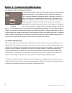
EMO circuit. This is accomplished via a “push to start” pushbutton located on the front panel. The button is iden-
tified by a label with the legend “DEPRESS BUTTON WHILE ENERGIZING MAIN BREAKER” The “push to
start” button energizes the EMO circuit power transformer from the input side of the input circuit breaker, which
provides the initial DC voltage to energize the under-voltage shunt trip of the input circuit breaker. For starting
GPI Series 2000 power conditioners equipped with SEMI S2-0200 option, follow these simple steps:
1. Make sure that the input circuit breaker is rotated fully to it’s farthest left position.
2. Make sure that the EMO pushbutton is in its operating position (turn in direction of arrow to disengage)
3. Press and hold the “push to start” button while rotating the input circuit breaker to the right
4. Verify that the “power on” LED on the front panel is illuminated
5. Release the “push to start” button
The power conditioner will now be operating normally and any connected loads may be energized. Please con-
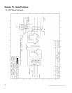
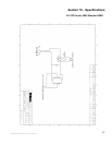
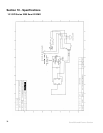
sult the schematics on pages 34, 35, and 36 of this manual for more information.
If a power conditioner equipped with the SEMI S2-0200 option is de-energized for
any reason (including a shunt trip due to EMO or interlock activation), mains power
will still be present at the input side of the input circuit breaker, and at the terminals
of the “push to start” switch. Working inside the power conditioner under these conditions may be
classified by SEMI S2-0200 guidelines as a Type 4 task. The task may be reduced to Type 1 if mains
power is de-energized and locked out at the facility source. The manufacturer recommends locking and
tagging out the facility source whenever it is necessary to enter the power conditioner enclosure.


