


Conditioned Power Center
23
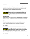
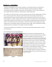
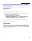
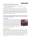
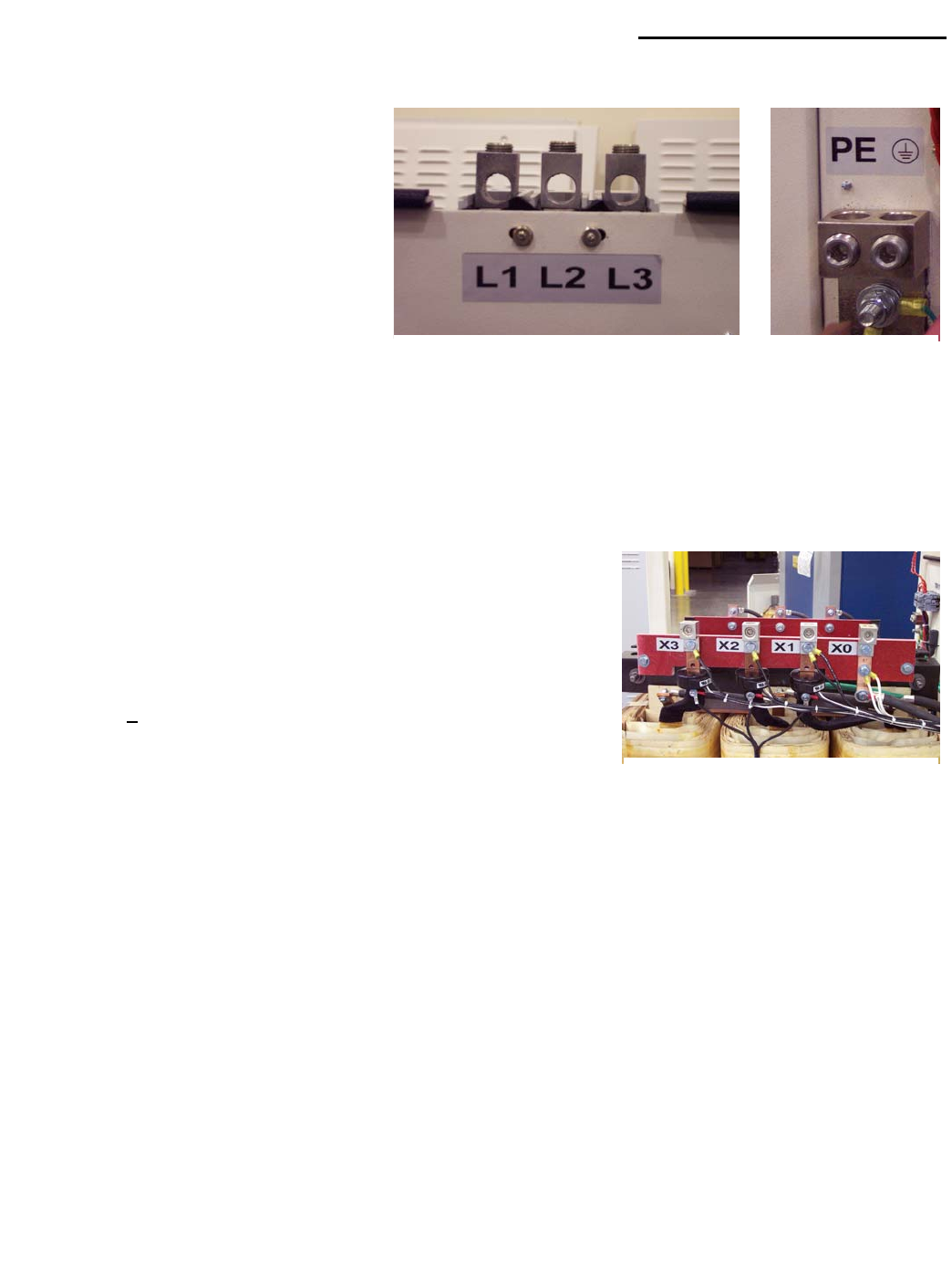
5.9 Input Power Connections
The three-phase input connection is made at
the lugs marked L1, L2, and L3 directly on the
main circuit breaker shown in Figure K to the
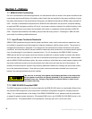
right. The safety ground connection is made
at the dual lug marked “PE” on the rear of the
panel immediately behind the main circuit
breaker shown in Figure L to the right. Locate
all connection points prior to committing to the
conductor lengths. Input conductor sizes are
determined by electrical code. For the convenience of the installer, the manufacturer has provided these, along
with other installation information, on the specification sheets included in Section 10 of this manual. Consult the
specification sheet for the conductor sizes required for the power conditioner.
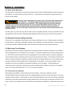
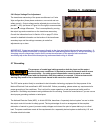
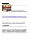
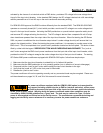
5.10 Output Power Connections
The load is connected to the lugs provided on the transformer's secondary
winding shown in Figure M to the right. Safety ground is connected to the
Neutral/Ground bus lug. This device provides a neutral ground bond. The
transformer secondary is also equipped with additional taps that allow the
installer to make fine adjustments to the output voltage of plus-or-minus
five percent ( +
5%) of nominal output to accommodate site-specific input
voltage differences. The power conditioner is shipped with the output
conductor connection lugs attached to the nominal output voltage
connection. If it is necessary to utilize the fine adjustment taps, the output conductors and the connection lugs
must be moved to the appropriate tap. For detailed connection diagrams, consult Section 10.4.
IMPORTANT NOTE! If this power conditioner is equipped with the basic metering or the power
management option, be sure to also move the associated current transformers to the appropriate
transformer secondary tap at the same time the output lug and output conductors are moved.
5.11 Models With Optional Line Cord/Output Receptacles
CPC series models 45 kVA and smaller may be equipped with optional input line cords. CPC series models of all
sizes may be equipped with optional output receptacles. If equipped with an input power cord, the installation
instructions discussed in paragraphs 5.9 will not apply. If equipped with output receptacles, the installation
instructions discussed in paragraph 5.10 may not apply. In all cases, it remains critical to observe all grounding
practices discussed in paragraph 5.7. If equipped with both line cord and receptacles, installation is a plug and
play operation. In any case be sure the site voltage matches the power conditioner configuration.
Section 5 - Installation
Figure K Figure L
Figure M