Conditioned Power Center
3
Caution Notice...............................................................................................................5
Section 1-General .........................................................................................................6
Section 2 – Safety
2.1 ANSI Warning Notices ..............................................................................7
2.2 Inherent Hazards.......................................................................................7
2.3 Alerts and Labels.......................................................................................7
2.4 Safety Interlocks........................................................................................9
2.5 Lockout/Tagout..........................................................................................9
2.6 Conformance with Regulations ...............................................................10
2.7 Product Liability .......................................................................................10
2.8 Emergency Contact Information .............................................................10
Section 3 – Product Overview
3.1 Product Purpose......................................................................................11
3.2 Standard Features...................................................................................12
3.3 Optional Features....................................................................................12
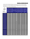
3.4 Feature/Model Matrix ..............................................................................13
Section 4 – Preparation
4.1 Unpackaging ...........................................................................................14
Section 5 – Installation
5.1 Location ...................................................................................................17
5.2 Conduit Landings ....................................................................................17
5.2.1Top Feed................................................................................17
5.2.2 Bottom Feed .........................................................................17
5.3 Outer Panel Removal..............................................................................18
5.4 Alternate Conduit Landing Locations......................................................18
5.5 Main Input Circuit Breaker.......................................................................18
5.5.1 Fixed Input Circuit Breaker ...................................................18
5.5.2 Programmable Circuit Breaker .............................................19
5.6 Isolation Transformer ..............................................................................19
5.6.1Transformer Primary Voltage Adjustment .............................20
5.6.2 Output Voltage Fine Adjustment...........................................21
5.7 Grounding................................................................................................21
5.8 Lockout/Tagout........................................................................................22
5.9 Input Power Connections ........................................................................23
5.10 Output Power Connections ...................................................................23
5.11 Optional Line Cord/Receptacles ...........................................................23
Section 6 - Operation
6.1 Restoring for Service...............................................................................24
6.2 Energizing the Power Conditioner ..........................................................24
6.3 Energizing the Load ................................................................................25
6.4 Orderly Shutdown....................................................................................25
Section 7 - Options
7.1 Passive Harmonic Filter ..........................................................................26
7.2 Basic Power Metering .............................................................................26
7.3 Power Management ................................................................................26
7.4 Phase Loss - Low Voltage Detect...........................................................27
7.5 External EMO Connector ........................................................................27
7.6 Seismic Anchorage .................................................................................27
7.7 SEMI S2-0200 .........................................................................................28
7.7.1 Input Power Conductor Restraints.......................................28
7.7.2 SEMI S2-0200 Compliant EMO...........................................28
Table of Contents


