


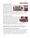
Conditioned Power Center
22
Specific locations for connecting the input and output safety ground conductors are discussed in Sections 5.9 and
5.10 that follow. These sections cover the information necessary to connect electrical wiring to both the main and
to the load. Please review both sections carefully before beginning the actual electrical installation. A
sophisticated electronic system will benefit greatly when all parts of the system and all system peripherals are
powered from a single power source. It is recommended that all parts of the system share this common power
source and its common, "clean" ground. Non-isolated code minimum input safety grounds are permitted.
Dedicated input safety grounding conductors are also permitted. They may be either isolated or non-isolated. If
an isolated input safety ground connection is desired, it should be a continuous, insulated, isolated conductor that
is routed directly back to the service entrance panel-board. The ground lug connection of the power conditioner
may also be connected to a separate grounding electrode or to building steel, provided that a separate low-
impedance grounding path (either copper conductor or conduit) is present and connects to the electrical system
ground. Excellent guidelines for grounding practices are also available by consulting the Federal Information
Processing Standards Publication (FIPS Pub. 94) published in 1983.
Connecting input wiring to the main source of power may require working inside
switchgear or distribution panelboards containing live voltages. Contact with live
voltages will result in injury or death. Working inside live switchgear is classified
as a Type 4 Task under SEMI S2-0200 guidelines. Prior to beginning input power connections, be sure to
follow any lockout/tagout procedures pertinent to your service equipment. Failure to observe this
warning may result in live voltages being present on conductors being connected to the input power
connections of the power conditioner.
Strict compliance with the following lockout/tagout procedure for the CPC series is
required to assure personnel safety when making input and output power
connections. Working inside the power conditioner with the lockout/tagout
engaged may be classified by SEMI S2-0200 guidelines as a Type 4 task if electrical power is not de-
energized and locked out at the source. If also locked out at the source, the task is reduced to Type 1.
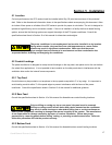
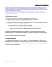
5.8 Lockout/Tagout Procedure
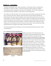
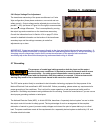
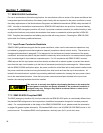
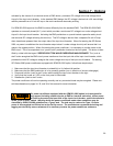
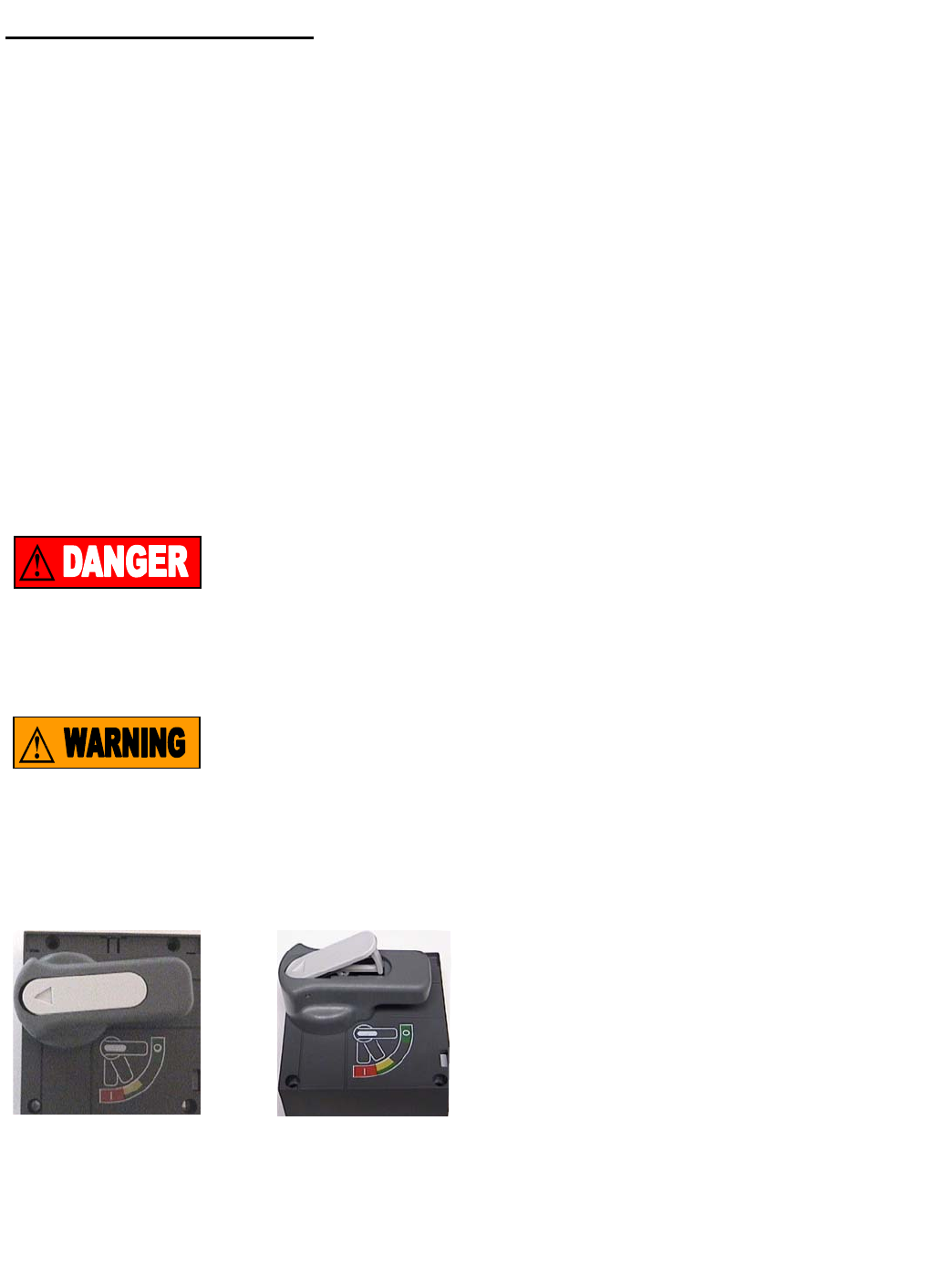
The rotary handle of the main breaker must be in the
horizontal (OFF) position to proceed. The rotary handle is
equipped with a hinged center insert clearly identified with
an arrow. See Figure I at left. Depressing the insert on
the arrow on the left hand side will cause the insert to
extend on the right. This will reveal a slot to accommodate
a locking device as shown in Figure J to the right. Place a
locking device in the slot and lock it. A warning label
(tagout) should be affixed to notify personnel that input power to the power conditioner has been locked out.
Section 5 - Installation
Figure I Figure J