


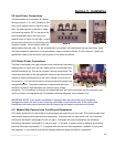
Conditioned Power Center
31
Section 8 - Troubleshooting/Maintenance
Prior to performing maintenance of any kind, lockout and tagout the electrical
power at both the facility source and the input circuit breaker. Under these condi-
tions, entering the equipment enclosure will be classified as a Type 1 task under
SEMI S2-0200 guidelines. Power must be locked out and tagged out at both locations prior to entering
the enclosure for maintenance purposes.
8.1.2.3 EMO Has Been Activated - The front panel EMO pushbutton latches in a closed position once it
has been depressed. Ensure that the EMO button has not been depressed by turning the button in the direction
of the arrows and allowing it to spring back to its normal operating position. If the power conditioner is equipped
with the external EMO option, further ensure that remote EMO buttons or connected external EMO circuits have
not been activated. Once all EMO buttons and circuits have been verified, rotate the circuit breaker handle to the
extreme counter-clockwise position and then rotate clockwise to the “On” position. If the circuit breaker once
again trips immediately, contact the manufacturer for further instructions.
8.1.2.4 Safety Interlocks Activated - Check both side panels of the power conditioner for proper instal-
lation and secure fit. Both panels must be firmly in place and securely fastened with the quarter turn fasteners
provided. A loose or improperly attached panel will allow the safety interlocks to activate and shunt trip the front
panel circuit breaker. Once the panels have been checked, rotate the circuit breaker handle to the extreme
counter-clockwise position and then rotate clockwise to the “On” position.
If the circuit breaker once again trips immediately, contact the manufac-
turer for further instructions.
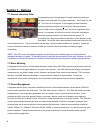
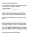
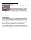
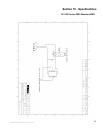
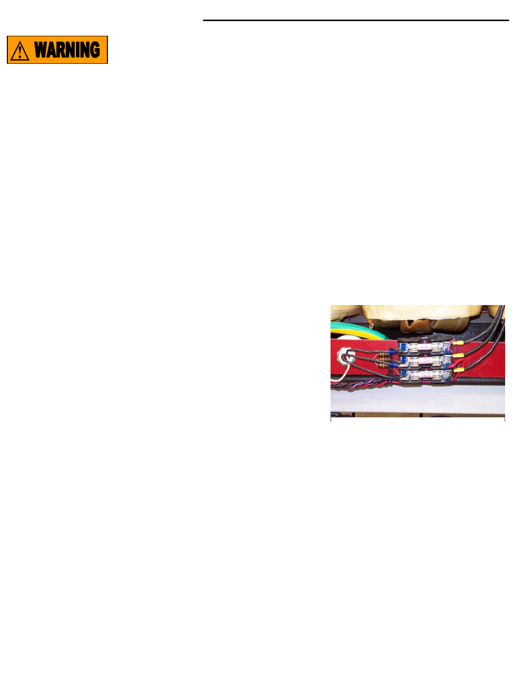
8.1.3 TVSS Fault LEDs Illuminate
If one or more TVSS Fault LEDs illuminate, it is an indication that the
TVSS components may be damaged. These components are protected
by fuses. The TVSS module and it’s associated fuses are located inside
the power conditioner enclosure, on the right side below the isolation transformer as illustrated in Figure P to the
right. The TVSS module itself is attached to the rear of the mounting panel. Three resistors are associated with
the fuses. The resistors function as “pull up” resistors to light the front panel LEDs should one or more of the
fuses open. The TVSS module, fuses, and resistors are accessed by removing one or both side panels as de-
scribed in Section 5.3.
The fuses may be checked for continuity using an ordinary multi-meter. Open fuses may be replaced on site us-
ing an Amptrap ATQ20, Time Delay, 10 kA IR, 500 VAC, 20A fuse or equivalent. Once the fuses have been
replaced, replace the side panels as described in Section 6.1 taking care to reattach the grounding straps. Once
completed, rotate the circuit breaker to the clockwise “On” position. If one or more of the TVSS Fault LEDs re-
illuminate, the fuses have opened once again. This indicates that the TVSS element is damaged and requires
replacement. Contact the manufacturer to order a replacement part.
Figure P