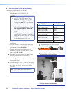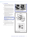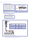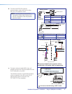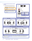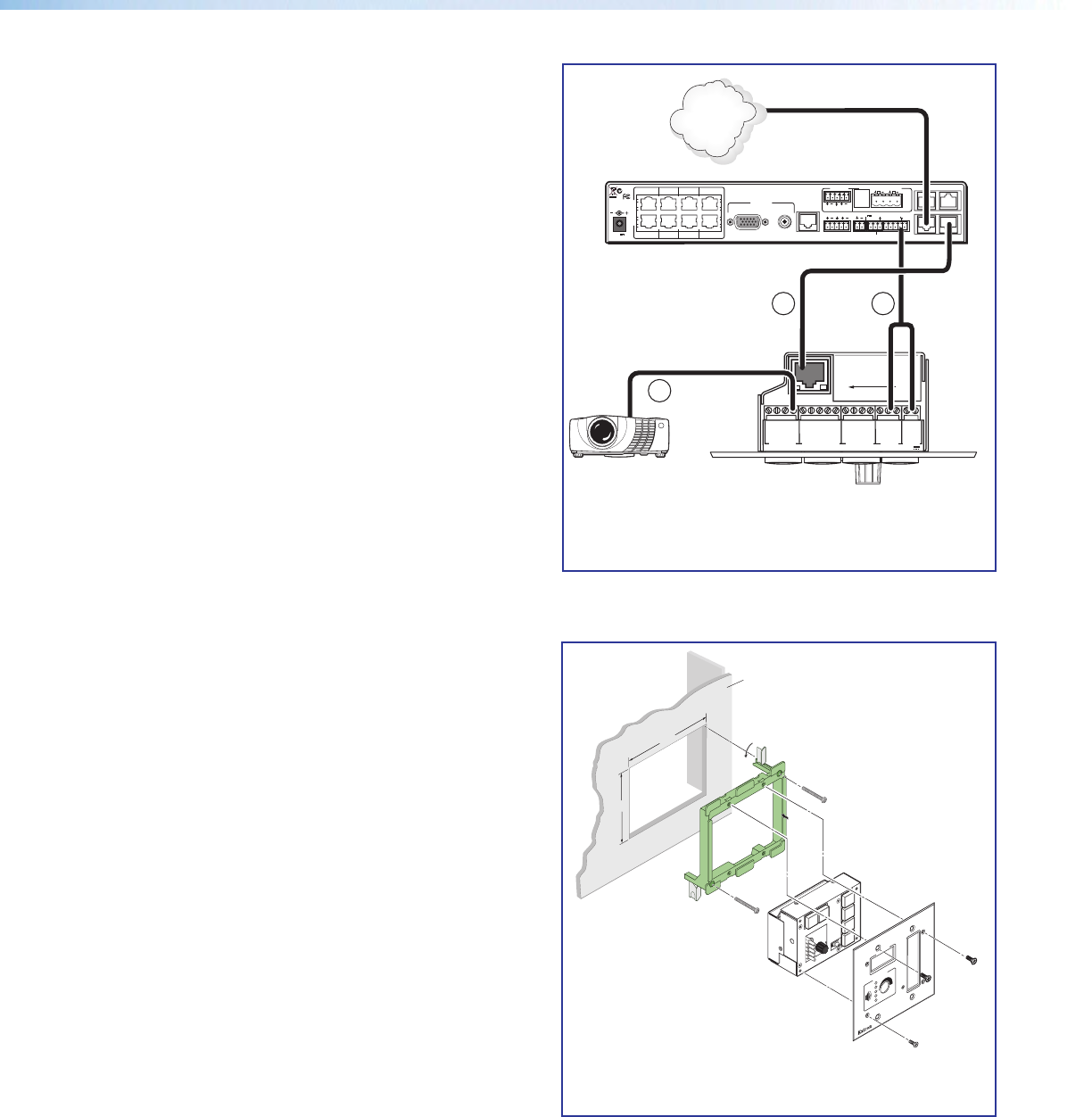
d. The connections between the MLC 104 IP Plus
and the PVS 305SA IP switcher should look like
the figure at right.
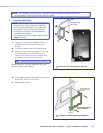
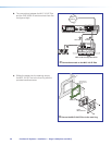
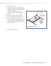
e. Sliding the cables into the opening, secure
the MLC 104 IP Plus to the mud ring with the
provided machine screws.
4.06"
3.75"
Wall Mouting
Bracket
Rotate locking arm
and insert into wall
opening.
Extron
MLC 104 IP Plus
Wall
OFF
ON
OFF
ON
CONFIG
DISPLAY
VOLUME
1
2
3
4
MLC 104 IP Plus
ô Secure the MLC 104 IP Plus to the mud ring
ò
Connections made to the MLC 104 IP Plus
PVS 305SA IP Switcher Rear Panel
LR
LR
LR
AUX AUDIO
INPUT 5
LINE OUT
VOICELIFT
RECEIVER
PAGING
SENSOR
DO NOT
GROUND
OR SHORT
SPEAKER
OUTPUTS
1B RGB
1A RGB
2B RGB
2A RGB
3B RGB
/VIDEO
4B RGB
/VIDEO
3A RGB
4A RGB
I
N
P
U
T
S
RS-232 MLC/IR
2/4/8
Ohms
CLASS 2 WIRING
AMPLIFIED AUDIO OUT
VOL/MUTE
Tx Rx IR 12V
10V50mA
POWER
RGB
VIDEO
OUTPUTS
CONTROL
N15779
12V
5A MAX
LAN 3
LAN 4
LAN 1
LAN 2
TCP/IP
Network
1
2
3
GROUND
+12V OUT
CM
GROUND
IR OUT
GROUND
SCP
GROUND
Tx
Rx
DISPLAY
RS-232/IR
A B C D E
COMM LINK
LAN
PRESS TAB WITH
TWEEKER TO REMOVE
A B
MLS
RS-232
POWER
12V
DIGITAL
I/O
IR IN
Tx
GROUND
Rx
+12V IN
MLC 104 IP Plus Right Side Panel
Projector
RS-232
and Power
4c 4a
4b
RS-232 Control
CAT 5 Cable
PoleVault IP Systems • Installation — Stage 2 (Wallplates and MLC)28


